Eureka AIR delivers breakthrough ideas for toughest innovation challenges, trusted by R&D personnel around the world.

Bipolar plate structure of fuel cell

A fuel cell and bipolar plate technology, applied in the direction of fuel cells, circuits, electrical components, etc., can solve problems such as multiple outlet opening areas, impact on fuel cell performance, and reduction of oxidant gas carrying capacity

Inactive Publication Date: 2019-04-12
DALIAN INST OF CHEM PHYSICS CHINESE ACAD OF SCI
View PDF13 Cites 3 Cited by
  • Summary
  • Abstract
  • Description
  • Claims
  • Application Information

AI Technical Summary

Problems solved by technology

Especially in the middle of the oxidant gas inlet, because it is necessary to reserve a space for the tensioning studs of the stack, the tie bars in the oxidant gas inlet here are adjusted accordingly, and are no longer parallel to the short side of the opening of the inlet and outlet. And the length of the tie rod increases, occupying more opening area of ​​the oxidant gas inlet and outlet than other tie rods
Due to the existence of tie bars, it will have the following adverse effects on the fuel cell: 1. Reduce the flow area of ​​the oxidant gas inlet and outlet, and correspondingly reduce the carrying capacity of the oxidant gas inlet and outlet for the flow of oxidant gas; 2. The flow field of the fuel cell corresponds to the oxidant gas The fluid flow state of roughly a triangular area downstream of each tie bar of the gas inlet is different from the flow state of the main body of the fuel cell flow field
These unfavorable factors will negatively affect the performance of the fuel cell

Method used


Image

  • Bipolar plate structure of fuel cell
  • Bipolar plate structure of fuel cell
  • Bipolar plate structure of fuel cell

Examples


Embodiment Construction

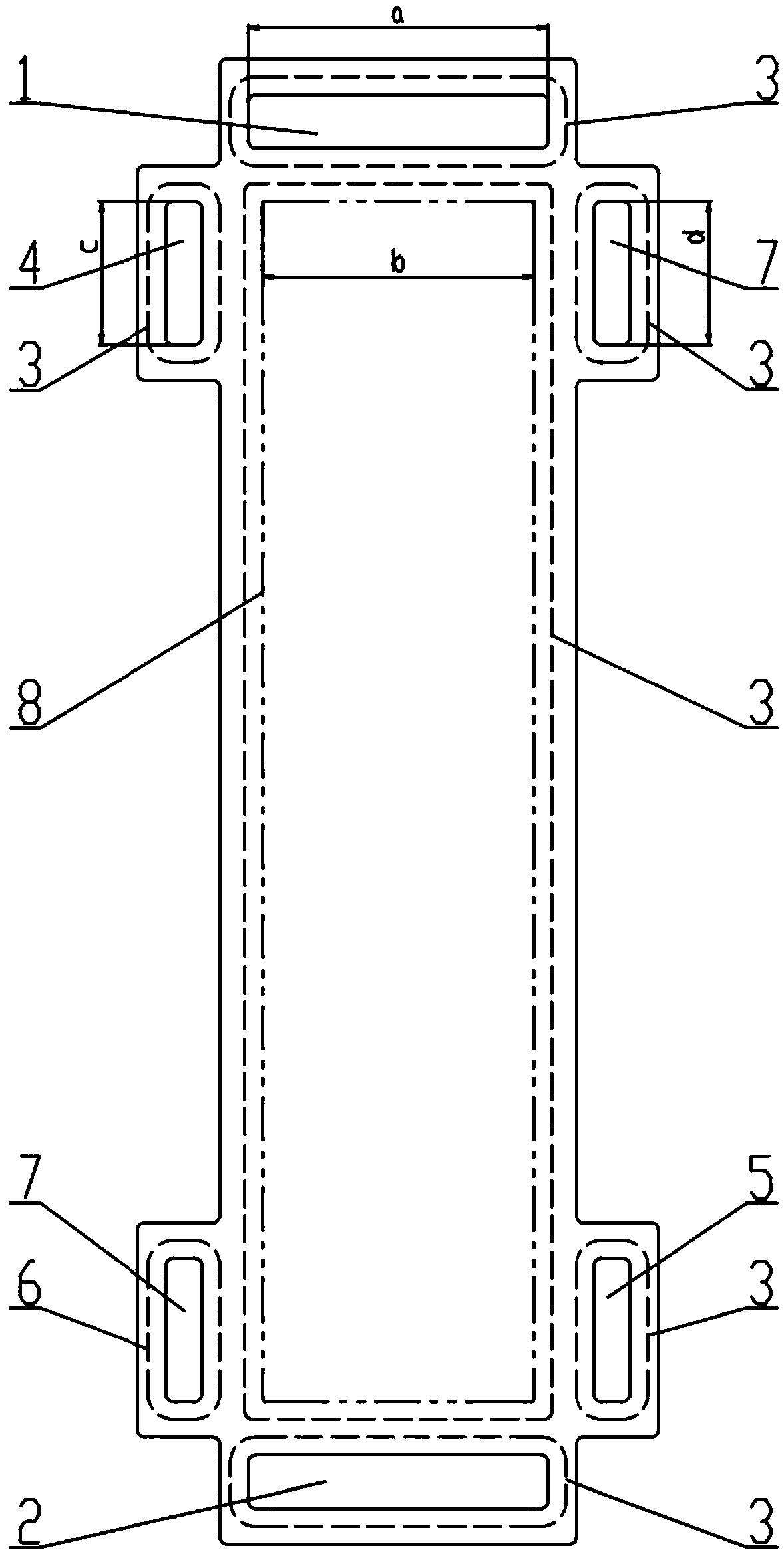
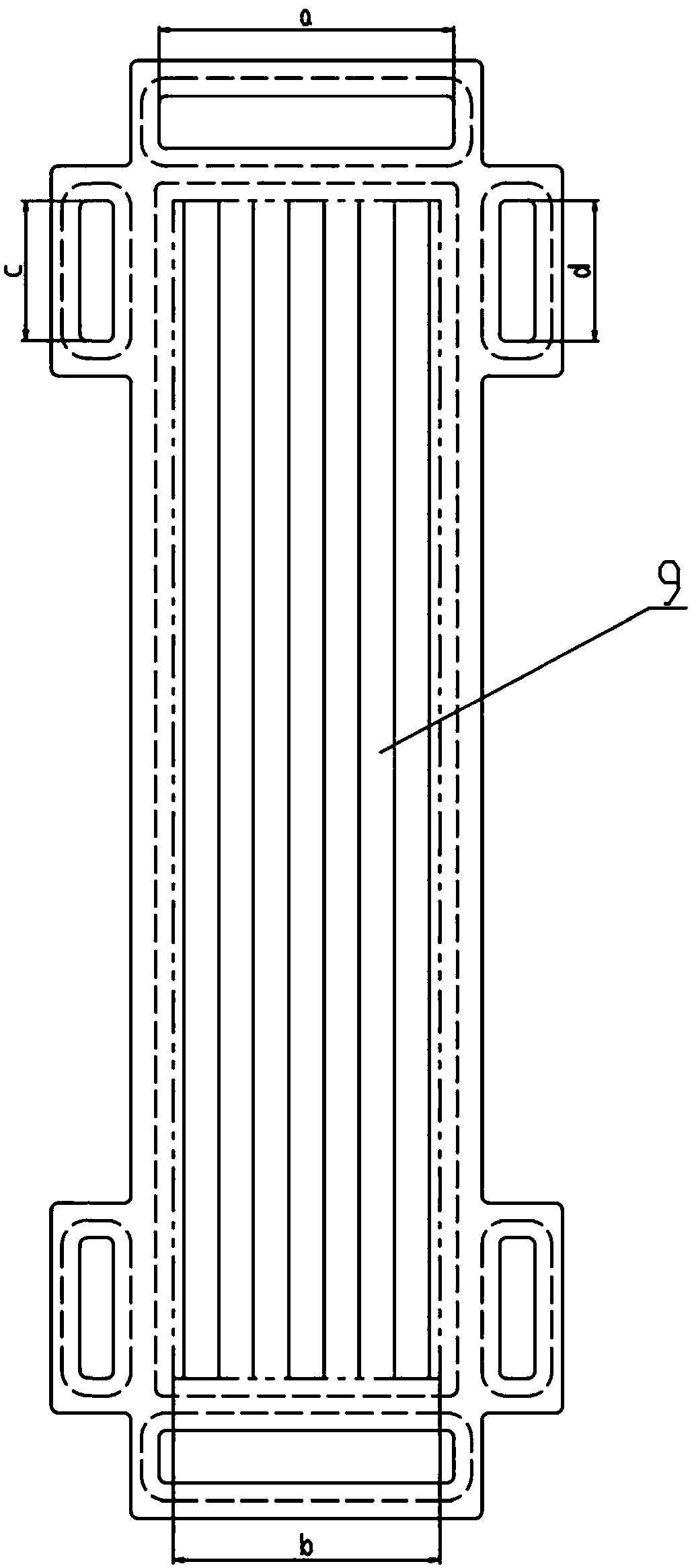
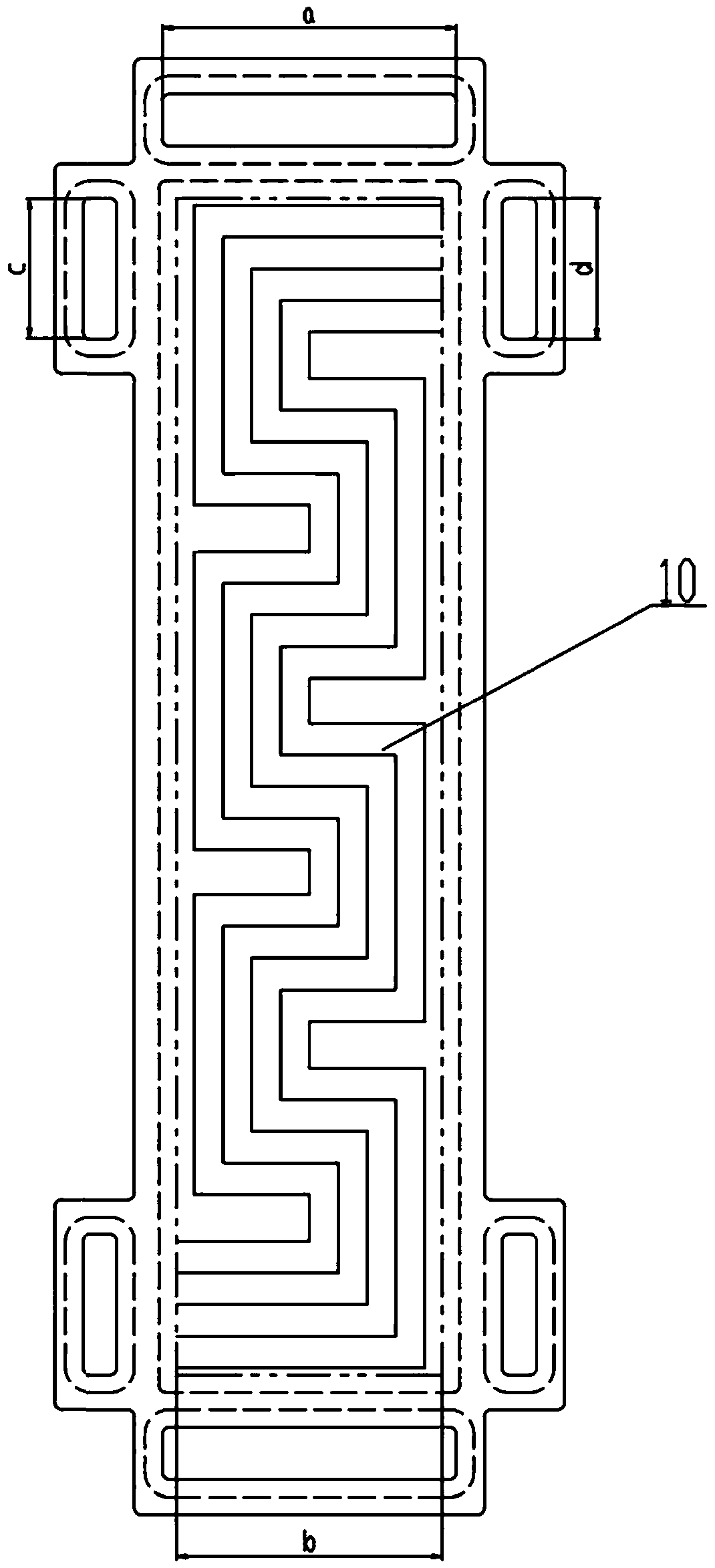
[0029] The layout of the fuel cell bipolar plate of the present invention includes the general arrangement of functional structures such as fuel cell flow field (including fuel gas flow field and oxidant gas flow field), fuel gas, oxidant gas, coolant and sealing structure on the fuel cell bipolar plate . The middle part of the fuel cell bipolar plate is the fuel cell flow field, which occupies most of the area of ​​the fuel cell bipolar plate. The fuel cell flow field is rectangular, the oxidant gas flow field is on one side of the bipolar plate, and the fuel gas flow field is On the other side of the polar plate, the size, shape and position of the two flow fields are the same, that is, the projections of the oxidant gas flow field and the fuel gas flow field on the middle plane of the two flow fields are coincident; On both sides of the side, the oxidant gas inlet and outlet are respectively arranged. In the length direction of the side adjacent to the fuel cell flow field,...


PUM

PropertyMeasurementUnit
lengthaaaaaaaaaa
widthaaaaaaaaaa

Abstract

The invention relates to a bipolar plate structure of a fuel cell. An oxidizing agent gas inlet and an oxidizing agent gas outlet are respectively formed in two sides of an opposite edge of a fuel cell flow field, a fuel gas inlet and a fuel gas outlet occupy two ends of a diagonal line at two sides of the other opposite edge of the flow field, and a cooling agent inlet and a cooling agent outletoccupy two ends of the other diagonal line. In a length direction of an edge, adjacent to the flow field, of the oxidizing agent gas, the width of the oxidizing agent gas is designed to be larger or equal to the width of the flow filed. In the bipolar plate layout of the fuel cell, the oxidizing agent gas enters the oxidizing agent gas flow field of the fuel cell through an oxidizing agent gas inlet to participate in electrochemical reaction and then enters the oxidizing agent gas outlet, the oxidizing agent gas and tail gas after electrochemical reaction are in direct-through states in the oxidizing agent gas flow field, the oxidizing agent gas and the tail gas after electrochemical reaction are uniform and consistent in distribution and flowing state in the oxidizing agent gas flow field, and the power generation efficiency on unit area is higher.

Description

technical field [0001] The invention relates to the technical field of fuel cells, in particular to a fuel cell bipolar plate structure. Background technique [0002] A proton exchange membrane fuel cell (PEMFC) relies on an electrochemical reaction to convert chemical energy stored in a fuel gas, such as hydrogen, directly into electricity. Proton exchange membrane fuel cell power generation has the characteristics of fast start-up at room temperature, high energy conversion efficiency, green and pollution-free exhaust gas, and safety. It can be used in fixed power stations, mobile power stations, aviation generators, marine generators, vehicle-mounted generators, and field emergency power supplies. , portable power supply, etc. At the end of 2014, Toyota officially released the passenger car Mirai using full-power proton exchange membrane fuel cells, officially opening the door to the commercial application of proton exchange membrane fuel cells. [0003] At present, fue...

Claims


Application Information

Patent Timeline
Patent Type & Authority Applications(China)
IPC IPC(8): H01M8/0258
CPCH01M8/0258Y02E60/50
Inventor 艾军侯明郑利民邵志刚
Owner DALIAN INST OF CHEM PHYSICS CHINESE ACAD OF SCI
Why Eureka
Eureka Blog
Learn More