Eureka AIR delivers breakthrough ideas for toughest innovation challenges, trusted by R&D personnel around the world.

Arbitrary mode eddy electromagnetic wave generation method based on time modulation array

A vortex electromagnetic wave, time modulation technology, used in the manufacture of antenna array devices, antenna arrays, antenna arrays that are individually powered, etc. problem, to achieve the effect of low cost

Active Publication Date: 2019-04-12
XIDIAN UNIV
View PDF10 Cites 6 Cited by
  • Summary
  • Abstract
  • Description
  • Claims
  • Application Information

AI Technical Summary

Problems solved by technology

However, planar phase plates, spiral phase plates, and helical parabolic antennas can only generate limited integer-order vortex electromagnetic waves, and it is difficult to flexibly steer the beam
Although the use of phased UCA can flexibly generate multiple modes of integer-order vortex electromagnetic waves and perform beam steering, it needs to be combined with multiple radio frequency chains, phase shifter networks and power dividers, so that the transmitter and receiver High energy consumption and high cost
And at present, the fractional order OAM beam can only be generated in the optical vortex and the acoustic vortex, and there is no solution for the generation of the fractional vortex electromagnetic wave in the radio frequency band.
This limits the practical application of vortex electromagnetic waves in any mode in the radio frequency band, and is also a problem to be solved for OAM to improve spectral efficiency in wireless communications.

Method used


Image

  • Arbitrary mode eddy electromagnetic wave generation method based on time modulation array
  • Arbitrary mode eddy electromagnetic wave generation method based on time modulation array
  • Arbitrary mode eddy electromagnetic wave generation method based on time modulation array

Examples


Embodiment Construction

[0030] The embodiments and effects of the present invention will be further described in detail below with reference to the accompanying drawings.

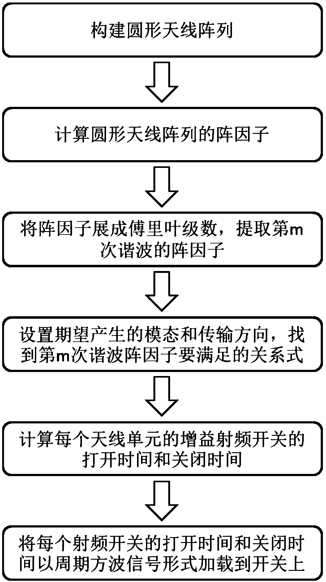
[0031] refer to figure 1 , the implementation steps of this embodiment are as follows:

[0032] Step 1, build a circular antenna array.

[0033] The condition that the electric fields of the array can be coupled with each other is that the spacing d of the array elements is between 0.5 times λ and 0.8 times λ, where λ is the wavelength of the electromagnetic wave. In order to make the mode number and purity of the generated vortex electromagnetic waves higher, the number N of antenna elements is set to be more than 8.

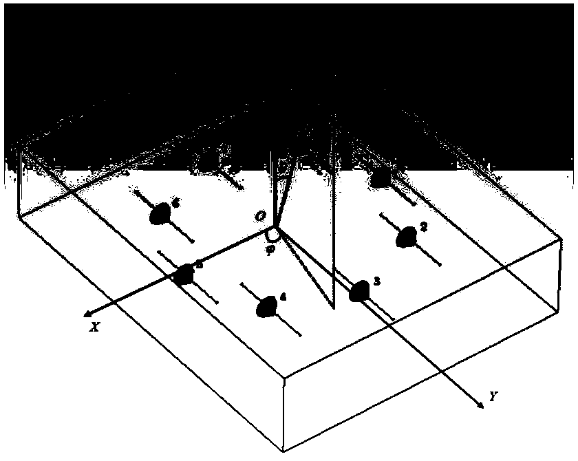
[0034] refer to figure 2 In this example, according to the condition of electric field coupling, the distance d between array elements is selected as 0.6 times λ, and the number N of antenna elements is 8, and these 8 antenna elements are arranged into a circular antenna array at equal intervals d. The radius ...


PUM


Abstract

The invention discloses an arbitrary mode eddy electromagnetic wave generation method based on a time modulation array, which mainly solves the problem that the prior art cannot generate fractional eddy electromagnetic waves in a radio frequency band and the beam alignment cost is high. A scheme for realizing the method comprises the steps of arranging a plurality of antenna elements into a circlewith equal spacing and connecting a radio frequency switch to each antenna element; calculating the array factors of the circular antenna array and expanding to extract the array factor of the mth harmonic; setting the desired direction of transmission and the desired mode to be generated in order to find the equation relationship between the amplitude part and the phase part found out from the mth harmonic array factor to calculate the gain of each antenna, the opening and closing time of the radio frequency switch, and then loading these parameters on the radio frequency switch of the corresponding antenna unit in the form of periodic square wave signal to generate the eddy electromagnetic wave. The invention can generate integer-order and fractional-order arbitrary mode eddy electromagnetic waves, has low beam alignment cost, and can be used for wireless communication and radar imaging.

Description

technical field [0001] The invention belongs to the technical field of wireless communication, and in particular relates to a method for generating vortex electromagnetic waves with arbitrary directional modes, which can be used for wireless communication and radar imaging. Background technique [0002] With the rapid development of wireless communication technology, the spectrum that can be allocated to wireless communication systems has become very crowded, and the problem of shortage of spectrum resources has become more and more serious, which has become a bottleneck for the continuous development of wireless communication and service applications. Dimensions such as amplitude, frequency, phase, and polarization state in the properties of electromagnetic waves have been used for signal characterization to improve transmission capacity. On the existing basis, it is impossible to continue to expand the channel capacity by increasing the dimensionality of electromagnetic wa...

Claims


Application Information

Patent Timeline
IPC IPC(8): H01Q21/00H01Q21/20H01Q21/29H01Q3/24H01Q3/34G06F17/11G06F17/14
CPCG06F17/11G06F17/141H01Q3/247H01Q3/34H01Q21/0087H01Q21/20H01Q21/293
Inventor 陈睿邹敏强李建东秦凡田正娟
Owner XIDIAN UNIV
Why Eureka
Eureka Blog
Learn More