Supercharge Your Innovation With Domain-Expert AI Agents!

Receiver for audio frequency/video frequency interlinked difference main line

A video bus and receiver technology, applied in the field of differential video bus receivers, can solve the problems of overcomplexity and high price

Inactive Publication Date: 2002-12-11
THOMSON CONSUMER ELECTRONICS INC
View PDF3 Cites 0 Cited by
  • Summary
  • Abstract
  • Description
  • Claims
  • Application Information

AI Technical Summary

Problems solved by technology

However, combining such conventional technologies to meet the overall requirements for a video bus receiver results in an overall system that may be too expensive and complex for use in a mass-produced consumer product such as a VCR (Video Cassette Recorder) or television receiver. Bus Receiver Design

Method used


Image

  • Receiver for audio frequency/video frequency interlinked difference main line
  • Receiver for audio frequency/video frequency interlinked difference main line
  • Receiver for audio frequency/video frequency interlinked difference main line

Examples


Embodiment Construction

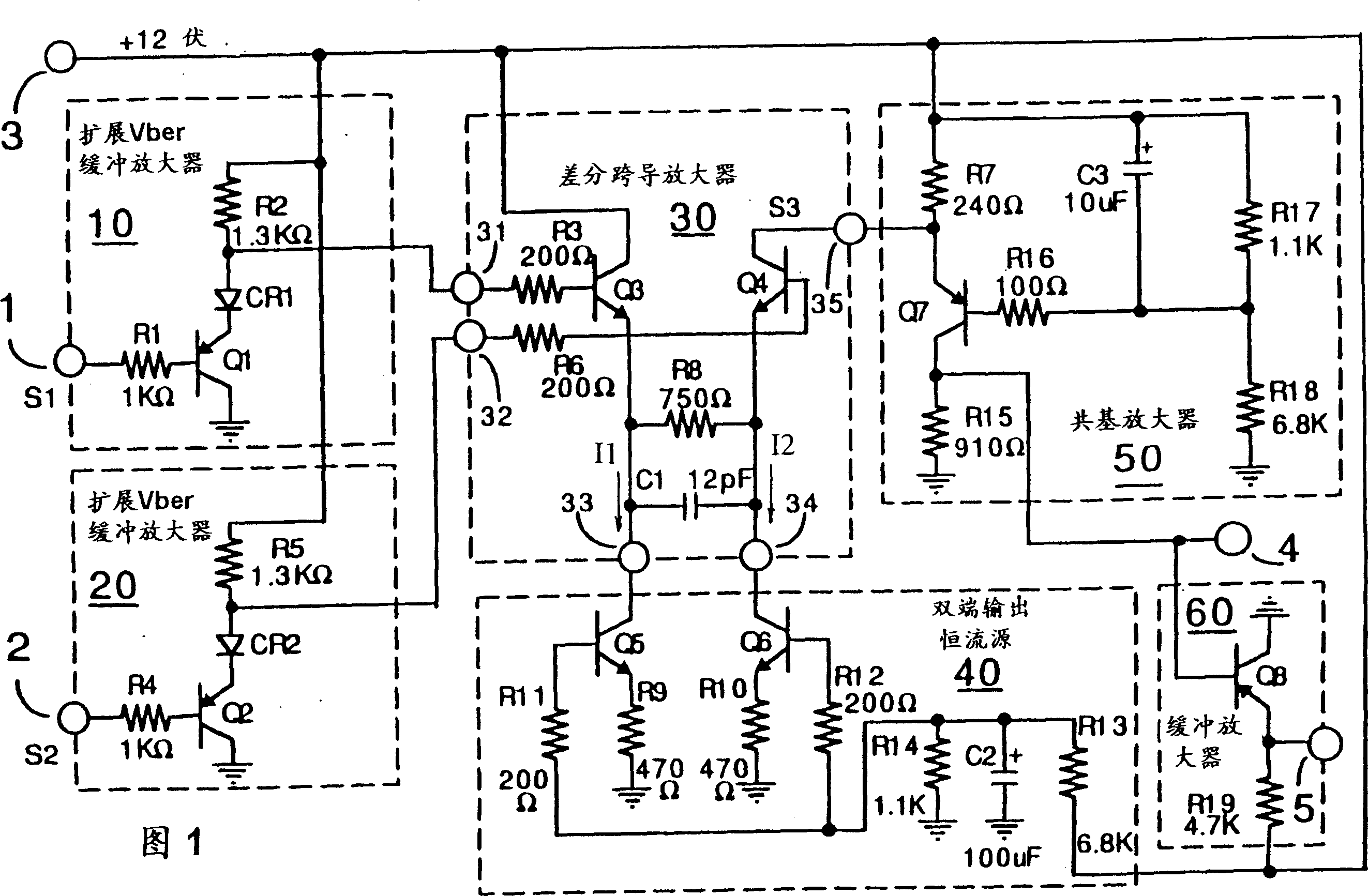
[0013] The video bus receiver of FIG. 1 includes a differential transconductance amplifier 30 having first and second input terminals 31 and 32 for receiving respective differential video input signals, having a fixed transconductance value (for the illustrated Exemplary component values ​​are approximately 1300 microohms) and have an output 35 for supplying a single-ended video output signal current.

[0014] A pair of buffer amplifiers 10 and 20 are provided to couple the first and second differential video input signals S1 and S2 (to respective inputs 1 and 2) to the differential transconductance amplifier 30 via respective diode switches CR1 and CR2. Corresponding inputs 31 and 32.

[0015] Changing the subject for a moment and explaining in more detail later, diode switches CR1 and CR2 provide (I) connection of differential input signals S1 and S2 to inputs 31 and 32 of amplifier 30 when power (+12 volts) is applied to the bus receiver. and (II) the dual function of disc...


PUM


Abstract

A transconductance amplifier (30) provides a video output signal (S3) proportional to the amplifier's transconductance (gm) and to the difference between the first (S1) and second (S2) differential video input signals supplied thereto. ) current. A pair of (10, 20) buffer amplifiers couple the video input signal (S1, S2) through respective diode switches (CR1, CR2) that provide Vber protection for the buffer transistors (Q1, Q2) and bus isolation in the powered-off state to the corresponding input terminals (31, 32) of the transconductance amplifier. An output circuit (50) regulates the output voltage of the transconductance amplifier (30) to a substantially constant voltage and converts the output signal current into an output signal voltage.

Description

technical field [0001] This invention relates generally to audio / video interconnect systems, and more particularly to differential video bus receivers suitable for use in such systems. Background technique [0002] Bus-oriented two-way audio / video interconnection systems are well known and are used, for example, to interconnect audio / video devices such as video tape recorders, laser disc players, television tuners, video cameras and video monitors. In a typical system, a common bus containing control, audio, and video signals is "daisy-chained" between various devices, driven by tri-state drivers so that the bus is said to be connected by all audio / video components All "shared". Such a system is described, for example, in US Patent 4,581,645, issued April 8, 1986 to Beyers Jr., entitled "DISTRIBUTED SWITCHED COMPONENT AUDIO / VIDEO SYSTEM." [0003] Standardization of audio, video, and control interconnects for television equipment has recently been considered by the Electro...

Claims


Application Information

Patent Timeline
Patent Type & Authority Patents(China)
IPC IPC(8): H04N5/14H03F3/19H03F3/68H03F3/45H03G1/00H04N5/44H04N5/765
CPCH03F3/19H03F3/45098H03F3/68H03F2203/45458H03G1/0023H04N5/148H04N5/765H04N21/426G11B20/10
Inventor T·D·格利C·M·怀特
Owner THOMSON CONSUMER ELECTRONICS INC
Features
  • R&D
  • Intellectual Property
  • Life Sciences
  • Materials
  • Tech Scout
  • Unparalleled Data Quality
  • Higher Quality Content
  • 60% Fewer Hallucinations
Learn More