A hot stamping hydraulic press system
A technology of hot stamping forming and hydraulic press, which is applied in the direction of fluid pressure actuation system components, presses, forming tools, etc. It can solve the problems of unable to press stably by the press, unable to cool the workpiece, etc., to solve insufficient cooling or uneven cooling , Solve the problem of thermal balance, the effect of slight vibration
- Summary
- Abstract
- Description
- Claims
- Application Information
AI Technical Summary
Problems solved by technology
Method used
Image
Examples
Embodiment 1
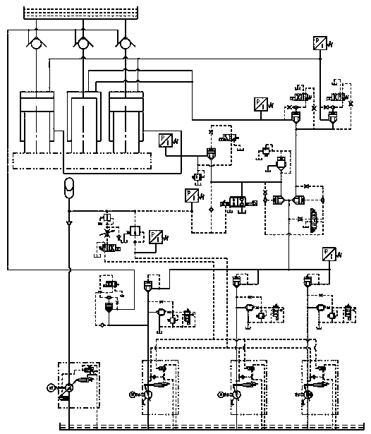
[0032] A hydraulic press system for hot stamping and forming includes: an external electric control system, and also includes: a main oil cylinder piping system, a main pump piping system, and a mold cooling control system;
[0033] The main pump piping system, the main pump piping system is controlled by an external electronic control system, and the main pump piping system is used to provide power to the compressor;
[0034] The main oil cylinder piping system, the main oil cylinder piping system is controlled by the main pump piping system, the main oil cylinder piping system is used for precise control of the pressure and speed when the press is pressed;
[0035] The mold cooling control system is controlled by an external electronic control system, and the mold cooling control system is used for workpiece cooling.
[0036] The system designed in the present invention can ensure the stable operation of the system when the press speed is increased to 1000mm / s; the hot stamping and f...
Embodiment 2
[0037] Embodiment 2: The difference based on embodiment 1 is;
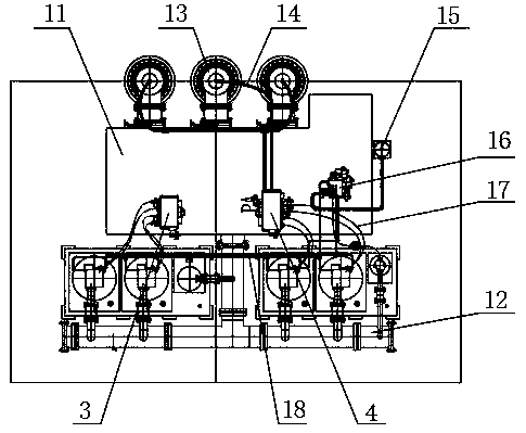
[0038] The main pump pipeline system includes: main oil tank 11, external T-shaped oil pipe 12, charging valve 13, charging valve control line 14, accumulator 15, pump external control valve block 16, main pump oil outlet line 17, and The main pump external control pipeline 18, three filling valves 13 are fixedly installed on the upper part of the main oil tank 11, and the filling valves 13 are connected to each other through the filling valve control pipeline 14. The filling valve control pipeline 14 and the main cylinder pipeline The system is fixedly connected. The lower end of the main oil tank 11 is fixedly connected to the upper end of the external T-shaped oil pipe 12, and the external T-shaped oil pipes 12 are connected to each other through the main pump external control pipe 18, and the main pump external control pipe 18 and the pump external control The valve block 16 is fixedly connected, the external T-s...
Embodiment 3
[0042] Embodiment 3: Based on the difference between Embodiments 1 and 2;
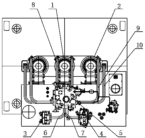
[0043] The main oil cylinder pipeline system includes: plunger cylinder 1, piston cylinder 2, pump control valve block A3, pump control valve block B4, main valve block 5, main valve block oil inlet pipe A6, main valve block oil inlet pipe B7, plunger cylinder The oil inlet pipe 8, the piston cylinder oil inlet pipe 9 and the piston cylinder oil return pipe 10, the main oil cylinder pipeline system adopts a symmetrical layout, the middle of the main oil cylinder pipeline system is fixedly installed with a plunger cylinder 1, and the inlets on the left and right sides of the plunger cylinder 1 The outlet end of the oil inlet pipe 8 of the plunger cylinder is fixedly connected, the inlet end of the oil inlet pipe 8 of the plunger cylinder is fixedly connected with the main valve block 5, and the piston cylinder 1 is fixedly installed on the left and right sides of the piston cylinder 2 in the main oil cylind...
PUM
 Abstract
Description
Claims
Application Information
 - R&D
- Intellectual Property
- Life Sciences
- Materials
- Tech Scout
- Unparalleled Data Quality
- Higher Quality Content
- 60% Fewer Hallucinations
Browse by: Latest US Patents, China's latest patents, Technical Efficacy Thesaurus, Application Domain, Technology Topic, Popular Technical Reports.
© 2025 PatSnap. All rights reserved.Legal|Privacy policy|Modern Slavery Act Transparency Statement|Sitemap|About US| Contact US: help@patsnap.com


