
Optical fiber and water guide laser coupling processing device and system

A processing device and optical fiber technology, applied in metal processing equipment, laser welding equipment, manufacturing tools, etc., can solve the problems of unsatisfactory laser processing depth, low laser total reflection efficiency, low laser output power, etc., and achieve stable laminar flow characteristics , Improve the coupling power of light and liquid, and improve the effect of coupling efficiency

Active Publication Date: 2021-07-27
NINGBO INST OF MATERIALS TECH & ENG CHINESE ACADEMY OF SCI
View PDF11 Cites 0 Cited by
  • Summary
  • Abstract
  • Description
  • Claims
  • Application Information

AI Technical Summary

Problems solved by technology

[0004] However, in the water-guided laser processing device in the prior art, when the liquid and the laser are coupled, the coupling power is still relatively low and the total reflection efficiency of the laser is relatively low, so that the output power of the laser is low, so the processing depth of the laser is still low. Can not meet the needs of some occasions

Method used


Image

  • Optical fiber and water guide laser coupling processing device and system
  • Optical fiber and water guide laser coupling processing device and system
  • Optical fiber and water guide laser coupling processing device and system

Examples


Embodiment 1

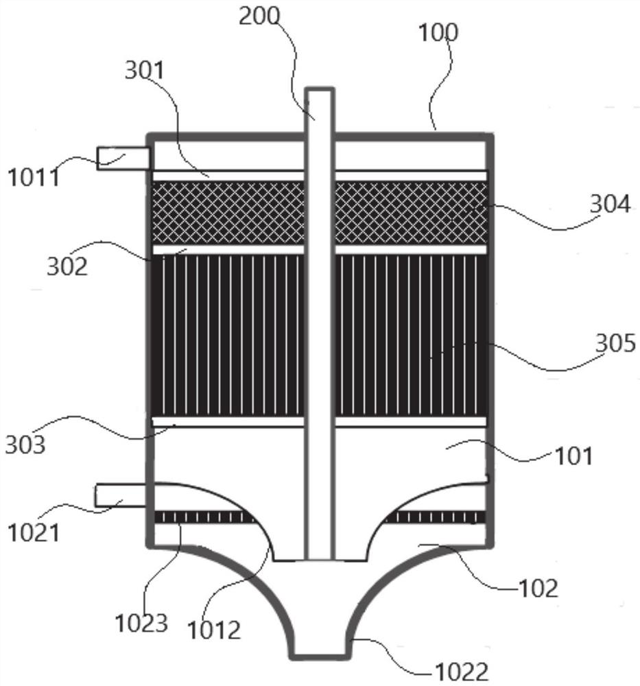
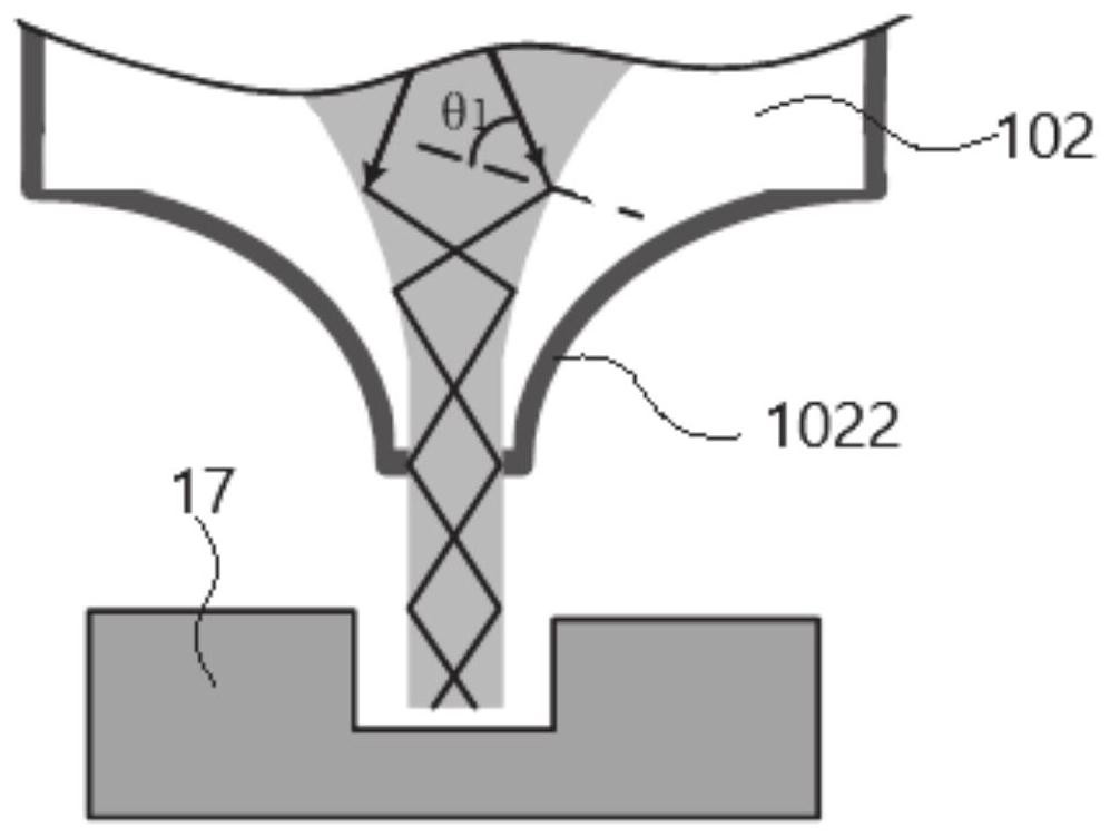
[0077] figure 1 Schematic diagram of the structure of the optical fiber and water guide laser coupling processing device provided in this embodiment, figure 2 The schematic diagram of water-guided laser transmission in the optical fiber and water-guided laser coupling processing device provided for this embodiment is combined below Figure 1~2 This embodiment will be specifically described.

[0078] Such as figure 1 As shown, the optical fiber and water-guided laser coupling processing device includes a laminar flow chamber 101 and a gas chamber 101 from top to bottom. In the laminar flow chamber 102, the first annular filter 301, the sponge body 304, the second annular filter 302, the guide tube 305, the third annular filter 303, and the layer The bottom end of the flow chamber 102 forms a first reduced diameter port. The optical fiber 200 is fixed in the laminar flow chamber 102 along the vertical direction, the upper end of the optical fiber 200 protrudes from the thro...

Embodiment 2

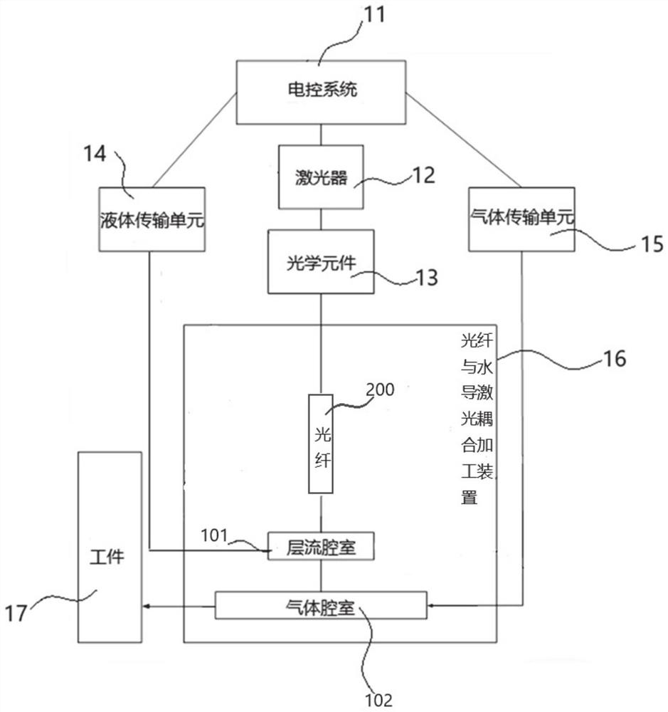
[0085] image 3 The structural frame diagram of the optical fiber and water guide laser coupling processing system provided for this embodiment, combined below image 3 This embodiment will be described.

[0086] Such as image 3 As shown, the optical fiber and water-guided laser coupling processing system includes: an electronic control system 11, a laser 12, an optical element 13, a liquid transmission unit 14, a gas transmission unit 15, and any of the optical fiber and water-guided laser coupling processing devices described above. 16;

[0087] The electric control system 11 is respectively electrically connected with the laser 12, the gas delivery unit 15 and the liquid delivery unit 14 for controlling the laser 12, the gas delivery unit 15 and the liquid delivery unit 14;

[0088] The optical element 13 is located between the laser 12 and the optical fiber and the water-guiding laser coupling processing device 16 for guiding the laser light generated by the laser 12 i...


PUM


Abstract

The application discloses an optical fiber and water guide laser coupling processing device, which belongs to the technical field of laser processing. The optical fiber and water guide laser coupling processing device includes a structural frame and an optical fiber; the structural frame includes a laminar flow chamber and a gas chamber from top to bottom; the optical fiber is fixed in the laminar flow chamber along the vertical direction; the laminar flow chamber is provided with Liquid inlet, the bottom wall of the laminar flow chamber is provided with a liquid outlet; an annular space is formed between the optical fiber and the laminar flow chamber; the gas chamber is provided with an air inlet, and the bottom wall of the gas chamber is provided with a water guide laser outlet . The device improves the total reflection efficiency of the laser and the coupling power between the laser and the liquid, thereby obtaining a high-power coupling laser, increasing the processing depth of the laser, and making the processing depth reach more than 10mm.

Description

technical field [0001] The application relates to an optical fiber and water guide laser coupling processing device and system, belonging to the technical field of laser processing. Background technique [0002] Water-guided laser processing technology is a technology in which a fine water jet guides the laser for processing. Due to the difference in the refractive index of the laser in water and in the air, the laser propagating in the water is totally reflected at the interface between the water beam and the air and is limited to Inside the water beam, the water beam acts as a light-guiding fiber. [0003] At this stage, the patent CN108262556A discloses a high-power coupled water-conducting laser processing device, which includes a liquid chamber, a window lens, a liquid chamber including a focusing lens, a support structure and a liquid vena contracta conduction device, and a liquid vena contracta conduction device The inner wall of the laser is coated with a total refl...

Claims


Application Information

Patent Timeline
Patent Type & Authority Patents(China)
IPC IPC(8): B23K26/00B23K26/36B23K26/064B23K26/06
CPCB23K26/00B23K26/06B23K26/36B23K26/064
Inventor 王恒张广义杨亚鹏张文武
Owner NINGBO INST OF MATERIALS TECH & ENG CHINESE ACADEMY OF SCI
Learn More