Screening equipment for rubber processing based on centrifugal force principle
A screening equipment and centrifugal force technology, applied in the field of rubber processing, can solve the problems of prolonging the working time of users, low screening efficiency, inconvenient use, etc., to achieve better screening effect and improve the screening effect
- Summary
- Abstract
- Description
- Claims
- Application Information
AI Technical Summary
Problems solved by technology
Method used
Image
Examples
Embodiment 1
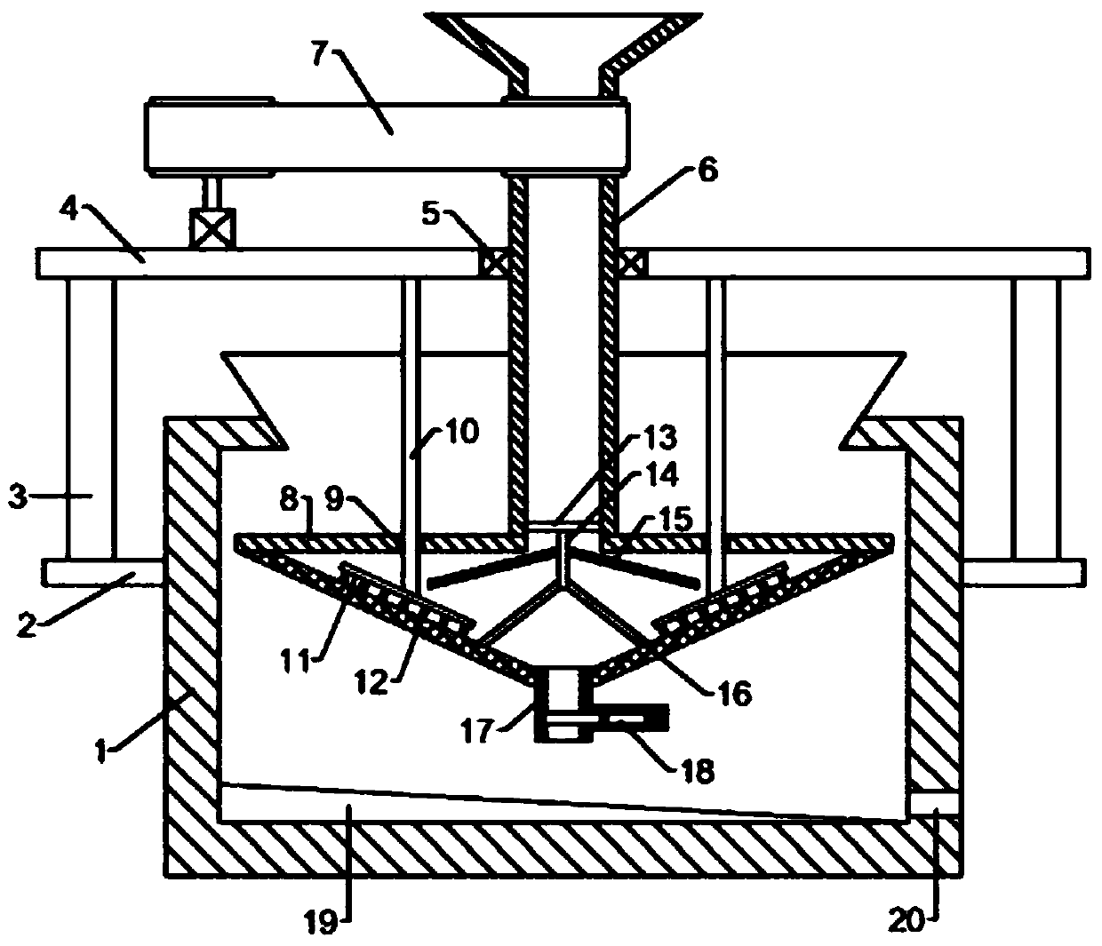
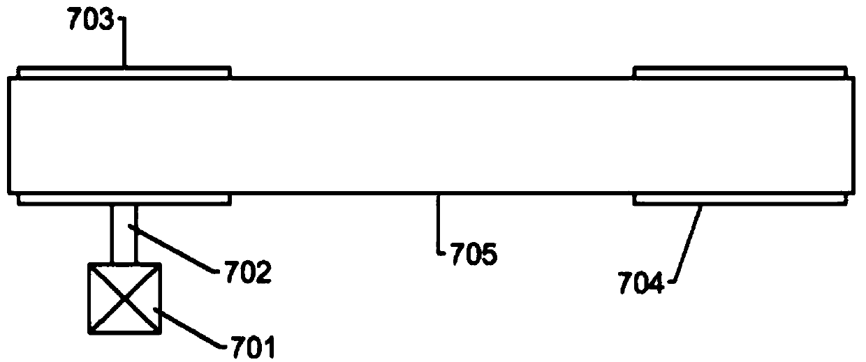
[0021] see figure 1 with figure 2 , in an embodiment of the present invention, a screening device for rubber processing based on the principle of centrifugal force, comprising a housing 1, two mounting seats 2 are symmetrically and fixedly connected to the outer wall of the housing 1, and support columns 3 are fixedly connected to the mounting seats 2 , the tops of the two support columns 3 are fixedly connected with a support plate 4, the middle of the support plate 4 is fixedly connected with a bearing 5, the inner ring of the bearing 5 is fixedly connected with a rotating sleeve 6, and the upper part of the rotating sleeve 6 is connected with a driving device 7. The driving device 7 includes a driving motor 701, a rotating shaft 702 is fixedly connected to the output shaft of the driving motor 701, a driving pulley 703 is fixedly connected to the top of the rotating shaft 702, and a driven pulley 704 is arranged outside the rotating sleeve 6, The driven pulley 704 is conn...
Embodiment 2
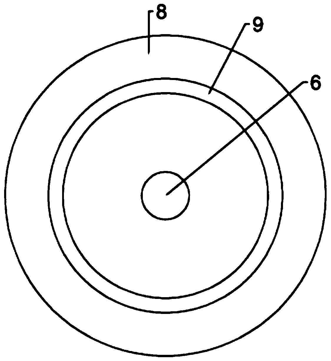
[0023] see figure 1 , figure 2 with image 3 , the bottom end of the rotating sleeve 6 is fixedly connected with a screening frame 8, the screening frame 8 is in the shape of an inverted triangular pyramid, the slope of the screening frame 8 is made of a filter screen; the upper side of the screening frame 8 is provided with an annular through hole 9. A connecting rod 10 passes through the annular through hole 9. The top end of the connecting rod 10 is fixedly connected to the support plate 4. The bottom end of the connecting rod 10 is fixedly connected to a tilting rod 11. The lower side of the tilting rod 11 is evenly arranged with a disturbance rod 12. The material is fed from the top of the rotating sleeve 6 and falls into the screening frame 8. Due to the continuous rotation of the rotating sleeve 6, the material at the bottom of the screening frame 8 is continuously thrown onto the slope of the screening frame 8 under the action of centrifugal force. It is filtered ou...
Embodiment 3
[0025] see figure 1 with Figure 4 , the bottom of the screening frame 8 is provided with a discharge channel 17, and the discharge channel 17 is provided with an electric valve 18. The electric valve 181 includes a horizontal column 181, and the horizontal column 181 is provided with a moving groove 182 with an opening facing left, An electromagnet 183 is arranged in the moving groove 182, a magnetic pole 184 is arranged on the left side of the electromagnet 183, and a moving plate 185 is connected to the left side of the magnetic pole 184, and the moving plate 185 is arranged through the discharge channel 17; the inner side wall of the moving groove 182 is symmetrical Offer two guide grooves 186, guide rod 187 is arranged in the guide groove 186, the other end of guide rod 187 is fixedly connected with moving plate 185, and guide rod 187 is connected with guide groove 186 right side by spring 188, when screening When there are many large particle materials that have not bee...
PUM
 Abstract
Description
Claims
Application Information
 - R&D
- Intellectual Property
- Life Sciences
- Materials
- Tech Scout
- Unparalleled Data Quality
- Higher Quality Content
- 60% Fewer Hallucinations
Browse by: Latest US Patents, China's latest patents, Technical Efficacy Thesaurus, Application Domain, Technology Topic, Popular Technical Reports.
© 2025 PatSnap. All rights reserved.Legal|Privacy policy|Modern Slavery Act Transparency Statement|Sitemap|About US| Contact US: help@patsnap.com


