Transfer manipulator for material handling and working method of transfer manipulator
A technology of manipulators and manipulator components, which is applied to conveyor objects, transportation and packaging, etc., can solve the problems of low operation accuracy and operation efficiency, inflexible plane manipulators, and high labor intensity. The effect of high degree of automation of the work process and high work efficiency
- Summary
- Abstract
- Description
- Claims
- Application Information
AI Technical Summary
Problems solved by technology
Method used
Image

Examples
Embodiment
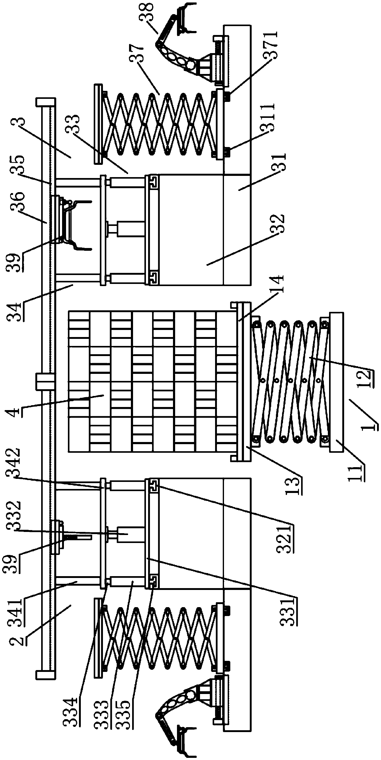
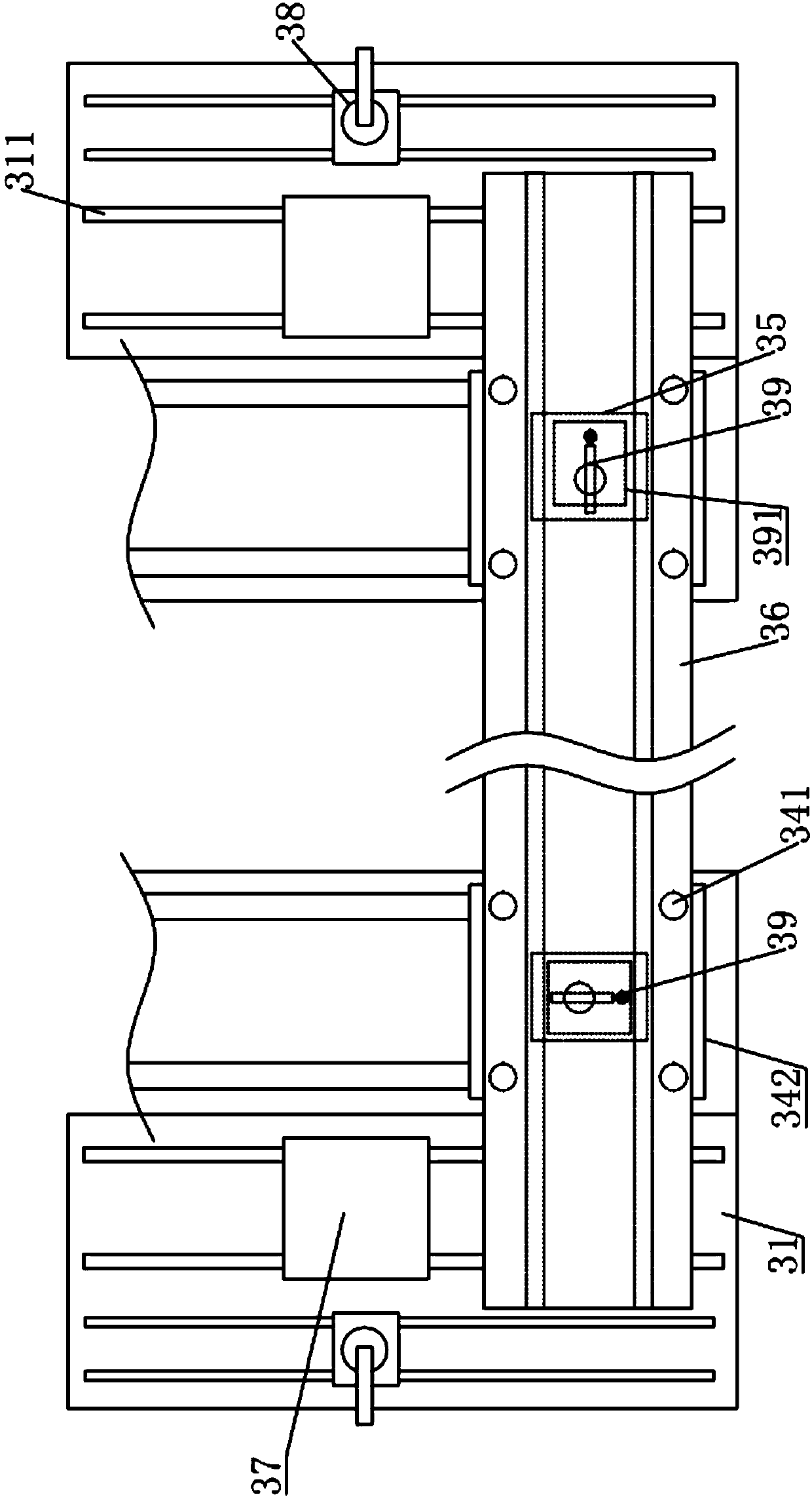
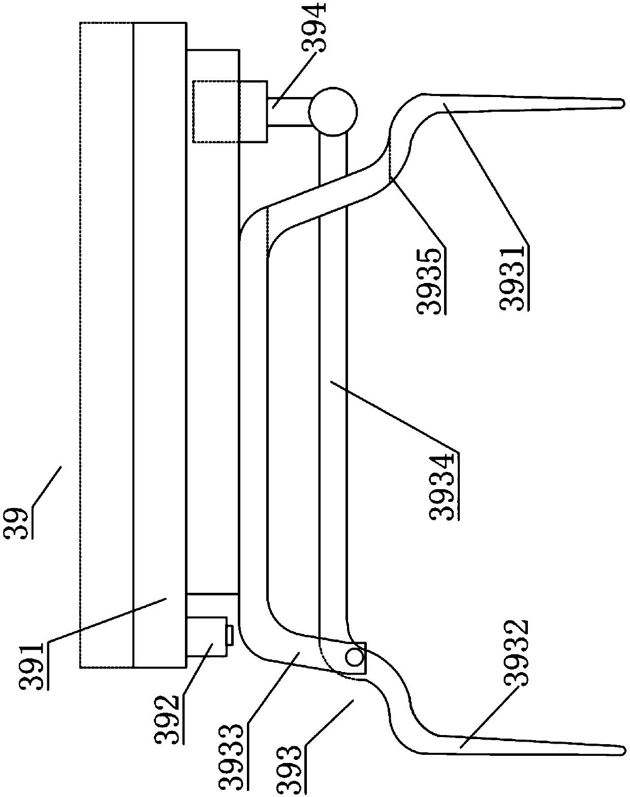
[0039] Such as figure 1 , 2 The transfer manipulator for material handling shown includes a first material support assembly 1, a first material handling manipulator assembly 2, a second material handling manipulator assembly 3 and a material 4, and the material 4 is arranged on the first material support assembly 1, The first material handling manipulator assembly 2 and the second material handling manipulator assembly 3 are symmetrically arranged on both sides of the first material support assembly 1; wherein, the first material handling manipulator assembly 2 and the second material handling manipulator assembly 3 include Base 31, support platform 32, first lifting drive assembly 33, first support frame 34, first linear module 35, first support plate 36, first material transfer assembly 37, first material transfer manipulator 38 and first Material handling manipulator 39, the support platform 32 is arranged on the side of the base 31 close to the first material support asse...
PUM
 Abstract
Description
Claims
Application Information
 - R&D
- Intellectual Property
- Life Sciences
- Materials
- Tech Scout
- Unparalleled Data Quality
- Higher Quality Content
- 60% Fewer Hallucinations
Browse by: Latest US Patents, China's latest patents, Technical Efficacy Thesaurus, Application Domain, Technology Topic, Popular Technical Reports.
© 2025 PatSnap. All rights reserved.Legal|Privacy policy|Modern Slavery Act Transparency Statement|Sitemap|About US| Contact US: help@patsnap.com