Pneumatic conveying equipment

A pneumatic conveying and lifting device technology, which is applied in the direction of conveying bulk materials, conveyors, transportation and packaging, etc., can solve the problems of uneven feeding, impeller stuck, material leakage, etc., and achieve the effect of simple structure and continuous material conveying

Pending Publication Date: 2019-04-16
肇庆市新大力设备制造安装有限公司
View PDF0 Cites 3 Cited by
  • Summary
  • Abstract
  • Description
  • Claims
  • Application Information

AI Technical Summary

Problems solved by technology

In the production process, the control and transportation of the material volume are completed separately by the mechanical control device and the pneumatic conveying device. This kind of pneumatic conveying that adopts the joint working method can control the material-air ratio of the conveying to achieve the maximum conveying capacity of the device, but now Some feeders (such as star feeders), the star feeder relies on the rotation of the impeller to unload, and there must be enough space between the impeller and the casing to allow the impeller to rotate in the casing, but When th

Method used


Image

  • Pneumatic conveying equipment
  • Pneumatic conveying equipment
  • Pneumatic conveying equipment

Examples


Embodiment Construction

[0022] The following will clearly and completely describe the technical solutions in the embodiments of the present invention with reference to the accompanying drawings in the embodiments of the present invention. Obviously, the described embodiments are only some, not all, embodiments of the present invention.

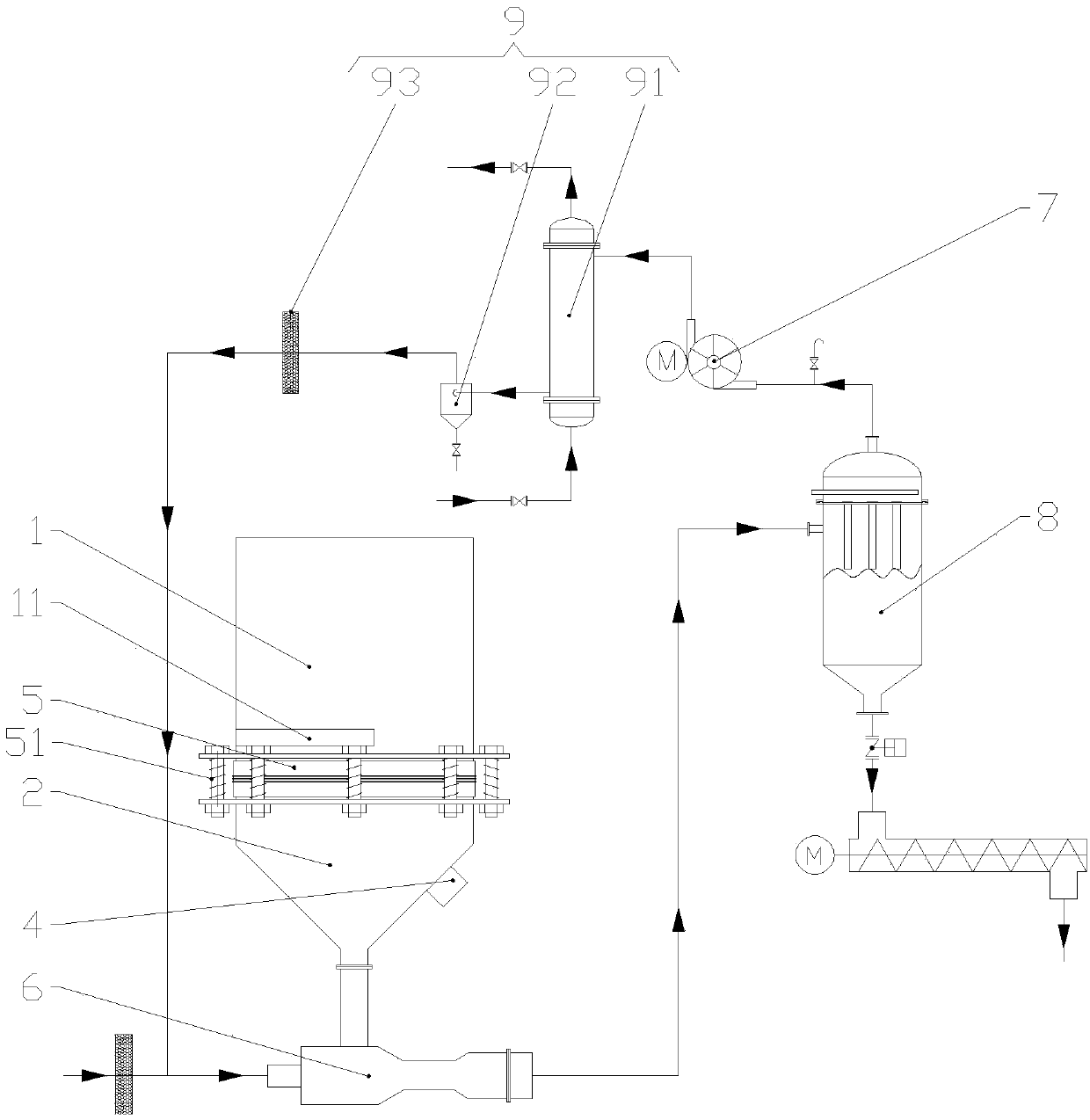
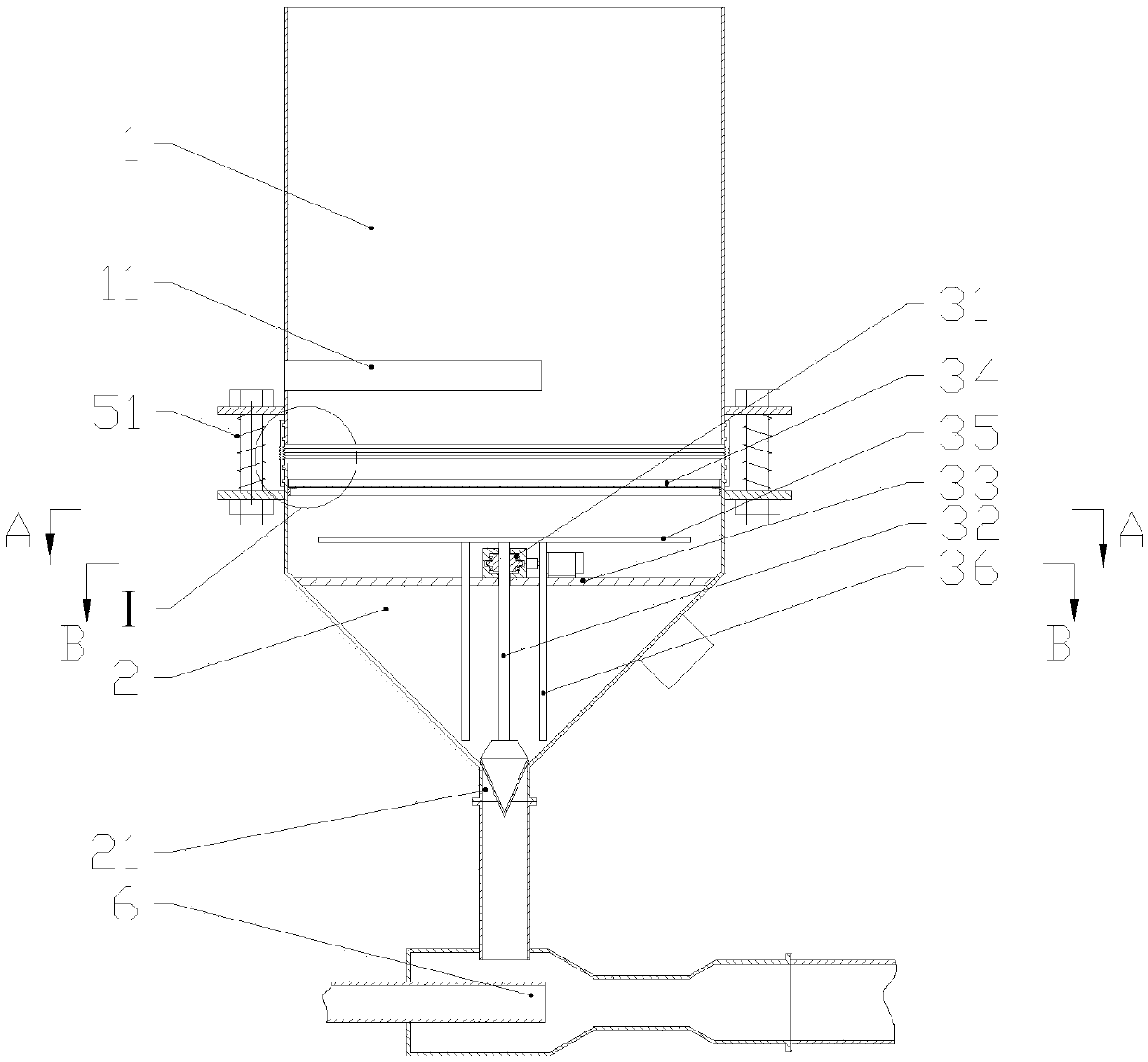
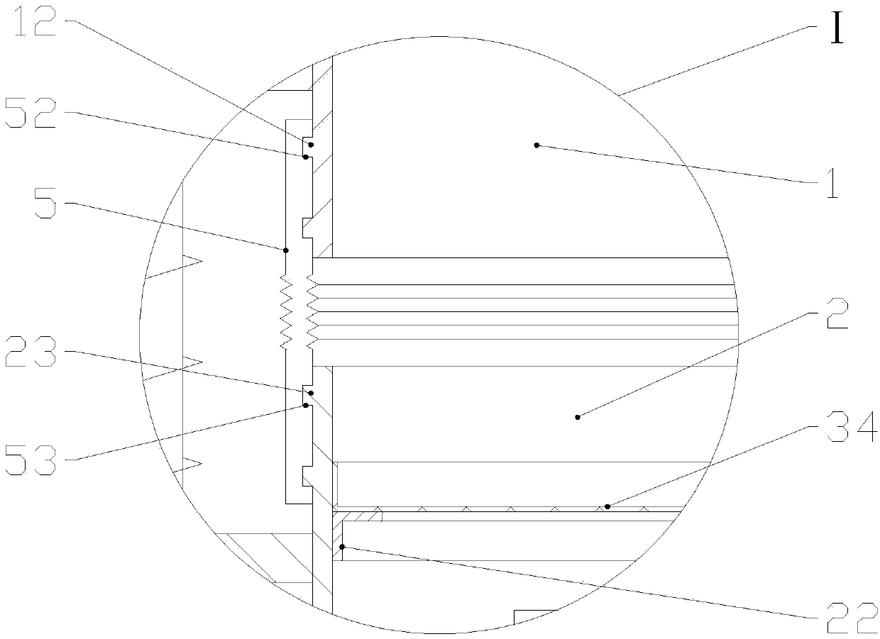
[0023] refer to Figure 1-7 , a kind of pneumatic conveying device of the present invention, it comprises feeding bin 1, hopper 2, material quantity adjusting device 3, vibrating motor 4, rubber sealing ring 5, mixing tank 6, blower fan 7, material storage device 8 and controller, all The above silo 1 is connected to the hopper 2 through a rubber seal ring 5, the flange of the upper silo 1 is connected to the flange of the hopper 2 through 8 bolts, and the 8 springs 51 are respectively sleeved on the 8 bolts and located Between the flange of the upper bin 1 and the flange of the hopper 2, the vibration motor 4 is fixed on the outer wall of the hopper 2, the controlle...


PUM


Abstract

The invention discloses pneumatic conveying equipment. The pneumatic conveying equipment comprises a feeding bin, a hopper, a material amount adjusting device, a rubber sealing ring, a mixing tank, afan and a material storage device, wherein the feeding bin is connected with the hopper through the rubber sealing ring, the lower end of the hopper is funnel-shaped, and a discharging port is formedin the bottom of the hopper; the material amount adjusting device comprises a driving lifting device, an adjusting rod and a cross beam, the cross beam is arranged in the hopper, the driving lifting device is fixed on the cross beam, the adjusting rod is connected with the driving lifting device and performs lifting motion under the driving of the driving lifting device, and the bottom of the adjusting rod is in an inverted cone shape; the bottom of the adjusting rod is suspended in the center of the discharging port, the discharging port is connected with the mixing tank, the mixing tank is connected with the material storage device, and the top of the material storage device is connected with the fan. By the adoption of the pneumatic conveying equipment, the function of adjusting the discharging amount of the discharging port in unit time and ensuring the uniform discharging of the hopper can be realized, thereby ensuring uniform conveying of material.

Description

technical field [0001] The invention relates to the technical field of material conveying, in particular to a pneumatic conveying device. Background technique [0002] Pneumatic conveying, also known as airflow conveying, uses the energy of airflow to transport granular materials along the direction of airflow in a closed pipeline, and is a specific application of fluidization technology. The structure of the pneumatic conveying device is simple, the operation is convenient, and it can be used for conveying in horizontal, vertical or inclined directions. In the production process, the control and transportation of the material volume are completed separately by the mechanical control device and the pneumatic conveying device. This kind of pneumatic conveying that adopts the joint working method can control the material-air ratio of the conveying to achieve the maximum conveying capacity of the device, but now Some feeders (such as star feeders), the star feeder relies on th...

Claims


Application Information

Patent Timeline
IPC IPC(8): B65G53/16B65G53/34B65G53/36
CPCB65G53/16B65G53/34B65G53/36
Inventor 苏伟恒姚达章范肇瑞
Owner 肇庆市新大力设备制造安装有限公司
Why Eureka
Try Eureka