Oil-water separator of circulating fluidized bed

A technology of oil-water separator and circulating fluidized bed, which is applied in the direction of liquid separation, separation methods, chemical instruments and methods, etc., can solve the problems of high separation cost, urgency, and low separation efficiency, and achieve secondary separation and improve efficiency , to enhance the effect of the interaction

Inactive Publication Date: 2019-04-16
NORTHEAST GASOLINEEUM UNIV
View PDF9 Cites 3 Cited by
  • Summary
  • Abstract
  • Description
  • Claims
  • Application Information

AI Technical Summary

Problems solved by technology

[0003] Oil-water separation is a key link in production in the petroleum and chemical industries, but the existing oil-water separators have disadvantages such as low efficiency, high operating costs, and complex structures, especially for oil-water mixtures with a high degree of emulsification. Some oil-water separation equipment has the following problems in the separation: first, the separation efficiency through mechanical movement is low; second, the separation cost is high by increasing the external force such as electric field or magnetic field; third, the interfacial tension is reduced by introducing a demulsifier, Auxiliary mechanical movement improves the separation efficiency, while increasing the cost, it will also cause environmental pollution
[0004] At present, in the process of oilfield development, oil displacement agents such as polymers and surfactants are usually added to carry out oil production, so that the produced fluid is in a stable emulsified oil state, which will lead to the oil-water mixture in the oilfield produced fluid or chemical sewage, It is difficult to achieve the ideal separation efficiency through traditional mechanical methods, so the demand for high-efficiency, low-energy oil-water separation technology and equipment is particularly urgent

Method used


Image

  • Oil-water separator of circulating fluidized bed
  • Oil-water separator of circulating fluidized bed
  • Oil-water separator of circulating fluidized bed

Examples


Embodiment Construction

[0024] Embodiments of the technical solutions of the present invention will be described in detail below in conjunction with the accompanying drawings. The following examples are only used to illustrate the technical solutions of the present invention more clearly, and therefore are only examples, rather than limiting the protection scope of the present invention.

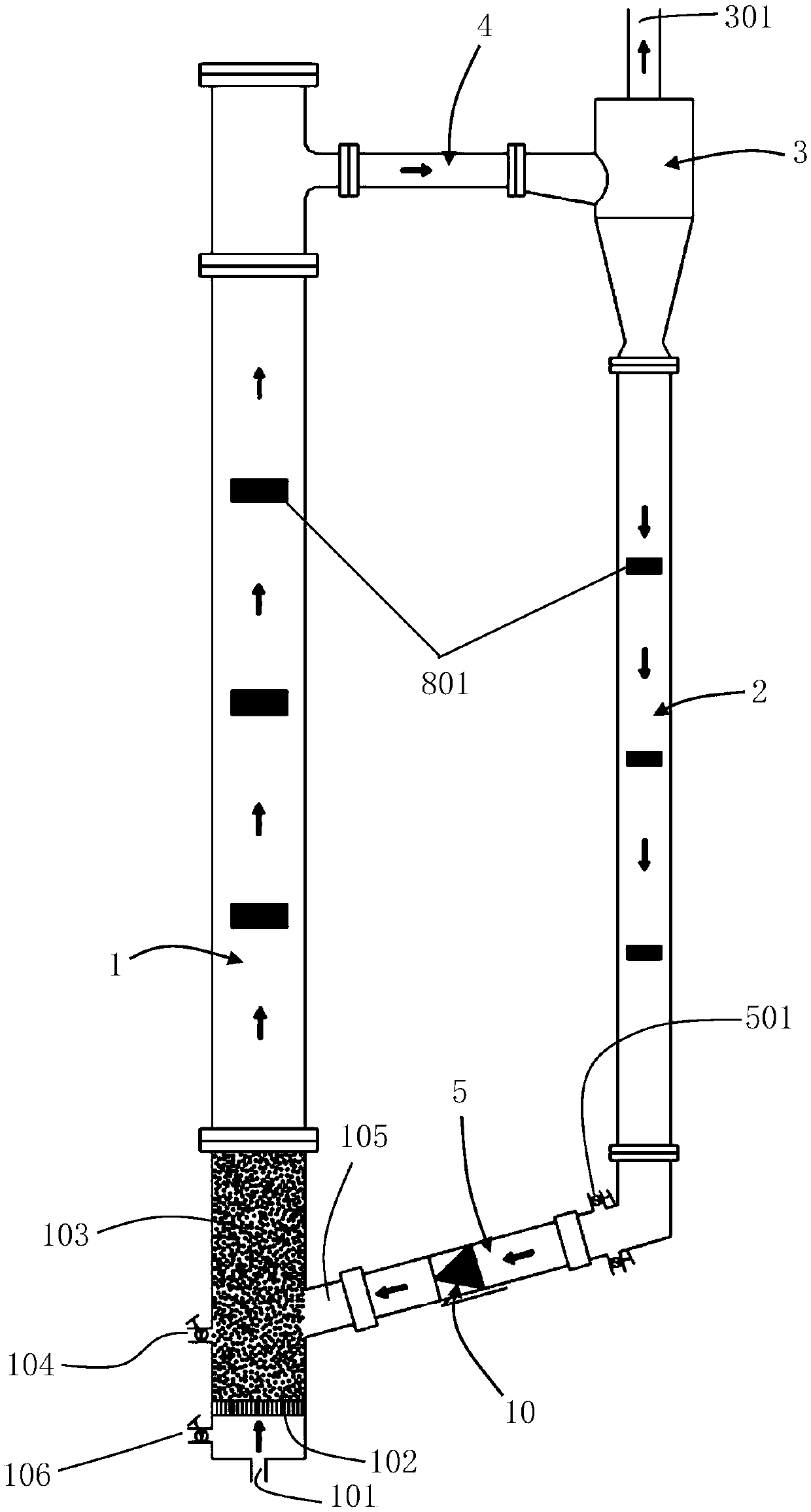
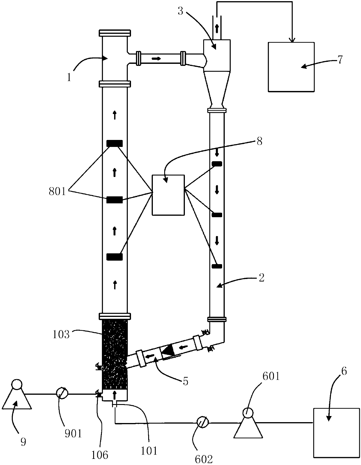
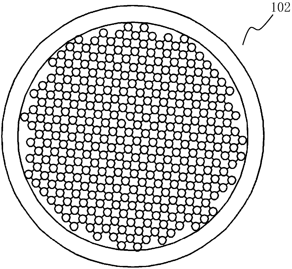
[0025] Such as figure 1 with figure 2 As shown, this embodiment discloses a circulating fluidized bed oil-water separator, including a riser 1 and a downcomer 2 arranged vertically, a liquid inlet 101 is arranged at the bottom of the riser 1, and a liquid inlet 101 is arranged at the bottom of the liquid inlet The top of 101 is provided with a liquid inlet distribution plate 102 (refer to image 3 ), the liquid inlet distribution plate 102 is in the shape of a mesh, and a number of through holes are arranged on it, and a number of oil-absorbing particles 103 are accumulated on the liquid-inlet distribution plate...


PUM

PropertyMeasurementUnit
diameteraaaaaaaaaa
particle diameteraaaaaaaaaa
densityaaaaaaaaaa

Abstract

The invention relates to an oil-water separator of a circulating fluidized bed, which comprises a lifting pipe, wherein a liquid inlet is arranged at the bottom of the lifting pipe, the liquid inlet is communicated with a liquid storage tank, a liquid inlet distribution plate is arranged above the liquid inlet, a plurality of oil absorption particles are stacked on the liquid inlet distribution plate, and a material inlet and outlet and a material return port are positioned on side wall of the lifting pipe, the material inlet and outlet and the material return port are all positioned above theliquid inlet distribution plate; a descending pipe, wherein the top of the descending pipe is provided with a liquid-solid cyclone separator, the liquid-solid cyclone separator is communicated with the upper part of the lifting pipe through a connecting pipe, and an overflow port at the top of the liquid-solid cyclone separator forms a first liquid outlet; a material return pipe, wherein one endof the material return pipe is communicated with the bottom of the descending pipe, the other end of the material return pipe is communicated with the material return port, and the material return pipe is provided with a second liquid outlet. According to the invention, the secondary separation of two phases of oil and water can be achieved through the adsorption action of oil absorption particlesand the centrifugation action of the liquid-solid cyclone separator, and the oil-water separation efficiency is improved.

Description

technical field [0001] The invention relates to the technical field of oil-water separation, in particular to a circulating fluidized bed oil-water separator. Background technique [0002] Oil-water separation of oilfield production fluid and chemical oily sewage is one of the main problems faced by petrochemical enterprises. There are three commonly used oil-water separation methods. One is to use the density difference between oil and water to adopt the sedimentation method of gravity separation; the other is to use the centrifugal force to use the difference in inertia of oil and water to form two internal and external cycles. Separation; the third is to use the principle of electric field separation, using the effect of electric field force to make the oil-water emulsion go through demulsification, aggregation and sedimentation, and then realize the separation of oil and water. [0003] Oil-water separation is a key link in production in the petroleum and chemical indus...

Claims


Application Information

Patent Timeline
Patent Type & Authority Applications(China)
IPC IPC(8): C02F9/02C02F1/40
CPCC02F1/285C02F1/38C02F1/40
Inventor 王淑彦田瑞超陈羽佳杨璎珞李萱
Owner NORTHEAST GASOLINEEUM UNIV
Why Eureka
Try Eureka