Sludge reduction device

A sludge and shell technology, applied in the direction of dewatering/drying/concentrating sludge treatment, can solve the problem of high treatment cost, and achieve the effect of ensuring evaporation effect, ensuring evaporation effect and reducing treatment cost.

Inactive Publication Date: 2019-04-16
ZHEJIANG JINMO ENVIRONMENT TECH CO LTD
View PDF1 Cites 1 Cited by
  • Summary
  • Abstract
  • Description
  • Claims
  • Application Information

AI Technical Summary

Problems solved by technology

[0004] The above-mentioned existing technical solutions have the following defects: this kind of device dries the sludge by means of electric heating. If this kind of device is used for a long time, it needs to digest electricity all the time to treat the sludge. higher processing costs

Method used


Image

  • Sludge reduction device
  • Sludge reduction device
  • Sludge reduction device

Examples


Embodiment Construction

[0040] The present invention will be described in further detail below in conjunction with the accompanying drawings.

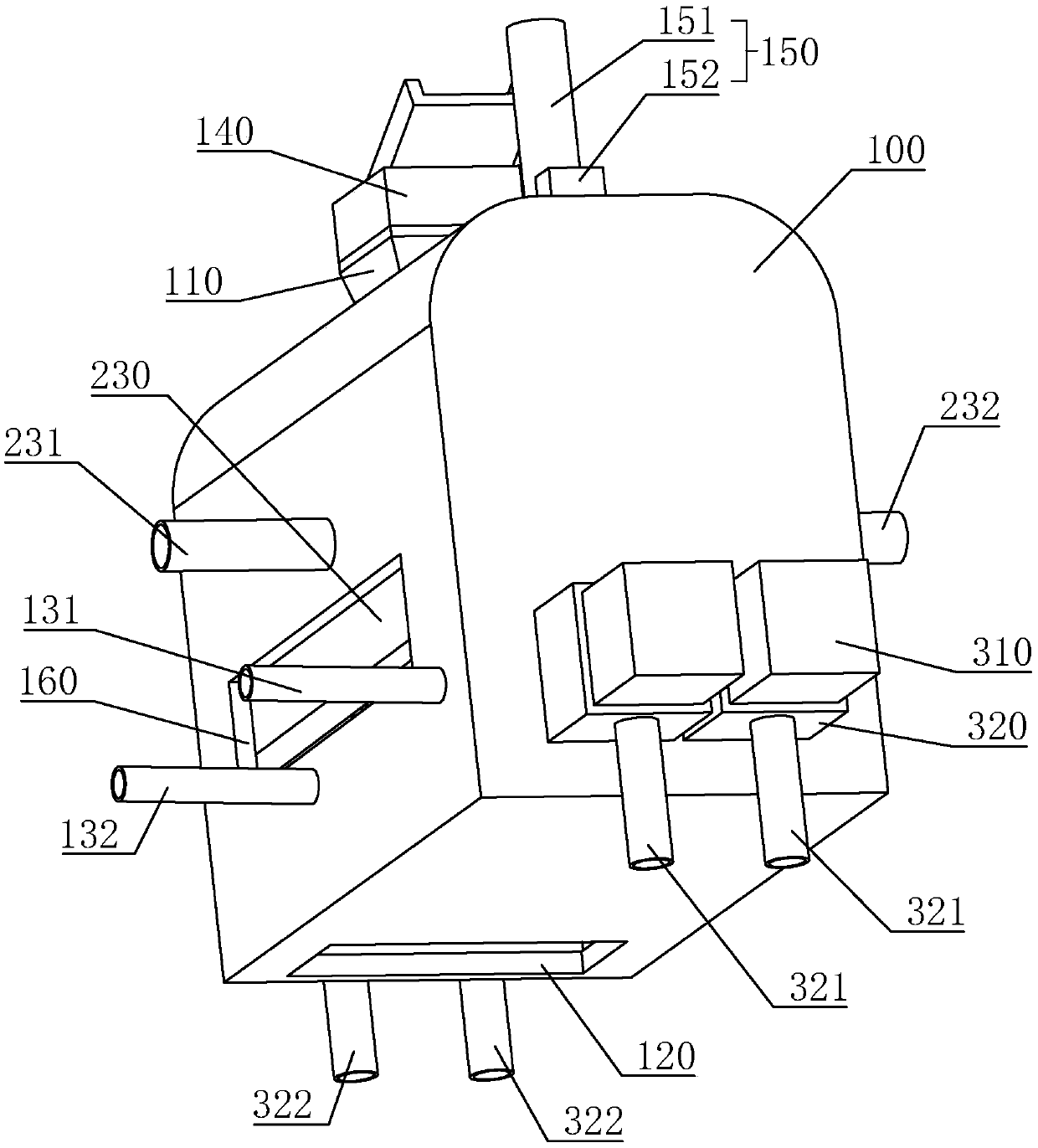
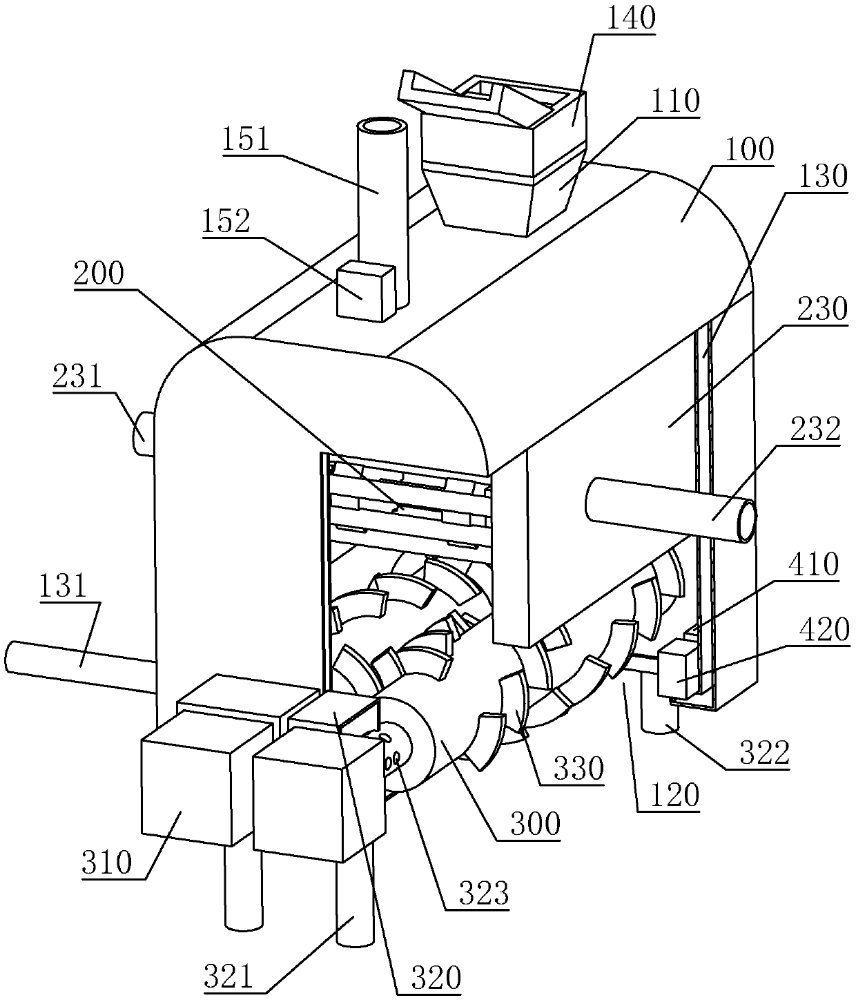
[0041] A sludge reduction device, referring to figure 1 , figure 2 , including a housing 100, a feed inlet 110 located on the upper side of the housing 100, and a discharge outlet 120 located on the lower side of the housing 100, the side wall of the housing 100 is a hollow structure, and the inside of the side wall of the housing 100 is formed cavity 130 , and a third inlet pipe 131 and a third outlet pipe 132 are installed on the casing 100 . Heat-insulating glass observation windows 160 are installed on both sides of the casing 100, and heat-insulating glass is installed inside it. An extruder 140 for extruding sludge is installed at the feed inlet 110, and an air extraction structure 150 is arranged on the top wall of the housing 100. The air extraction structure 150 includes an air extraction pipe 151 and an air exhaust fan 152, 151 is installed on t...


PUM


Abstract

The invention relates to the technical field of solid waste processing devices, and relates to a sludge reduction device which comprises a shell, a feed port in the upper side of the shell, and a discharge port in the lower side of the shell. A conveying belt is arranged at the position, located on the lower side of the feed port, in the shell. The conveying belt comprises a plurality of hollow pipes and hinges which are alternately arranged in parallel. Thermal medium boxes are arranged on the inner wall of the shell. The two thermal medium boxes are provided with a first inlet pipe and a first outlet pipe respectively. Rails are arranged on the side walls of the thermal medium boxes. The hollow pipes are arranged on the rails. The thermal medium boxes are provided with driving assembliesfor driving the hollow pipes to move. The top wall of the shell is provided with a suction structure. The sludge reduction device has the advantages that a thermal medium is introduced into the thermal medium boxes through the first inlet pipe, heat is transmitted between the hollow pipes and the sludge when the hollow pipes convey the sludge, and the effect of evaporating sludge water is achieved; by means of the device, heating and dewatering can be conducted on the sludge through a low-grade heat source, and the sludge reduction processing cost is reduced.

Description

technical field [0001] The invention relates to the technical field of solid waste treatment equipment, in particular to a sludge reduction device. Background technique [0002] Sludge is a product in the sewage treatment process. It is a solid, semi-solid and liquid waste. Its amount accounts for about 0.3%~0.5% of the sewage treatment volume. In addition to containing ash and a large amount of water (95%~ 99%), it also contains a large amount of organic matter, pathogenic microorganisms, bacteria, parasite eggs, volatile substances, heavy metals, salts, and plant nutrients (nitrogen, phosphorus, potassium), etc. It is bulky, perishable, and easily causes secondary pollution. [0003] At present, production enterprises generally transport the sludge out after initial dehydration. The Chinese invention patent with the publication number CN107586002A discloses a sludge drying treatment device, which includes a drying pipe body, two supports supporting the drying pipe body, ...

Claims


Application Information

Patent Timeline
Patent Type & Authority Applications(China)
IPC IPC(8): C02F11/13
CPCC02F11/12
Inventor 许以农彭辉陆斌黄兆建
Owner ZHEJIANG JINMO ENVIRONMENT TECH CO LTD
Why Eureka
Try Eureka