Self-powered active and passive composite rotational inertia drive control system

A technology of moment of inertia and drive control, applied in vibration suppression adjustment, spring/shock absorber, mechanical equipment, etc. Effects of stability and energy saving

Pending Publication Date: 2019-04-16
QINGDAO TECHNOLOGICAL UNIVERSITY
View PDF0 Cites 7 Cited by
  • Summary
  • Abstract
  • Description
  • Claims
  • Application Information

AI Technical Summary

Problems solved by technology

However, in the process of technical research and practice, people found that since the active control device needs external energy to drive the work, when the engineering structure is damaged, the power supply is accidentally cut off, which will lead to the complete failure of the active control device.
[0006] To sum up, the structural vibration control system plays an indispensable role, but the existing structural vibration control system has the following deficiencies: First, the translational TMD control device can only control the translational motion of the structure but not the rotary shimmy The control is invalid. Although the translational AMD control device can control the rotary shimmy, the control efficiency is extremely low and cannot meet the requirements of use; Complex frequency modulation has low control efficiency and poor effect on some complex structures, and has disadvantages such as low robustness, low controllability, and small application range; third, the control system has small application range, limited control force output, and control The effect is limited, and the energy utilization rate of the control system cannot be guaranteed, which cannot meet the needs of economy; fourth, although the active (rotation) control device can solve the above three problems, there is a risk of complete failure of the control system for unexpected energy cut-off

Method used


Image

  • Self-powered active and passive composite rotational inertia drive control system
  • Self-powered active and passive composite rotational inertia drive control system
  • Self-powered active and passive composite rotational inertia drive control system

Examples


Embodiment Construction

[0033] The present invention will be further described below in conjunction with accompanying drawing.

[0034] This embodiment takes the simple pendulum structure model as the structure of the prototype of the basic mechanical model;

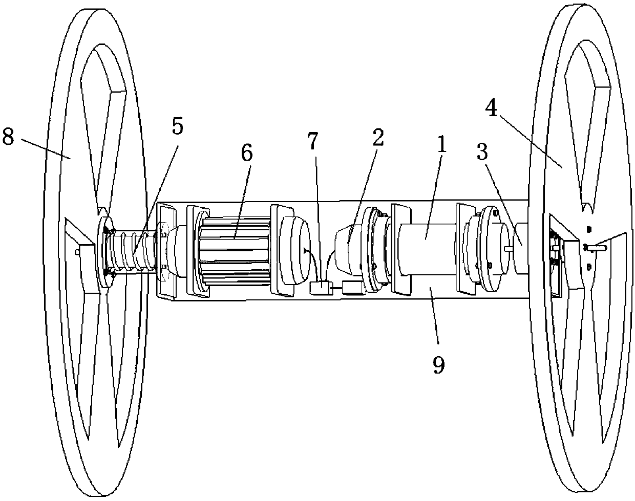
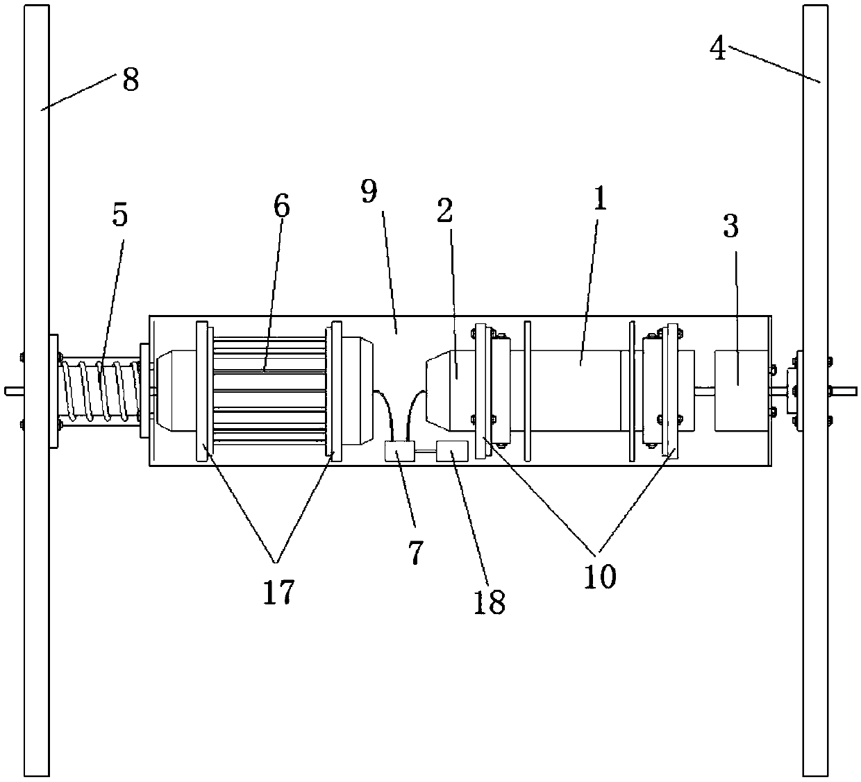
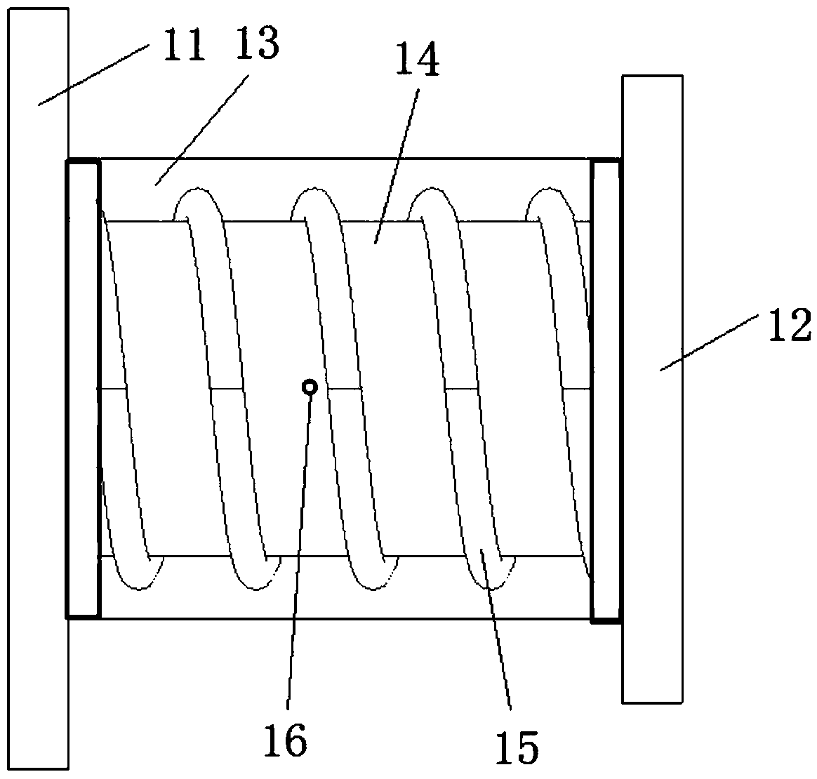
[0035] like Figure 1-4 As shown, the self-powered active-passive compound moment of inertia drive control system of the present invention includes an active output module and a passive output module. The active output module includes a driver 1, an encoder 2, a transmission 3 and an active moment of inertia disc 4; the passive output module Including torsional damping box 5, generator 6, energy storage unit 7 and passive moment of inertia disk 8;

[0036] A system lumen 9 is arranged between the active moment of inertia disc and the passive moment of inertia disc, and the active output module and the passive output module are symmetrically distributed along the center of the system lumen; the controlled structure 19 is fixed at the center of ...


PUM


Abstract

The invention relates to the field of vibration suppression in the system and discloses a self-powered active and passive composite rotational inertia drive control device. The device comprises an active output module and a passive output module, wherein the active output module includes a driver, an encoder, a transmission, and an active rotational inertia disc; the passive output module includesa torsional variable damping box, a generator, an energy storage unit and a passive rotation inertia disc; a system pipe cavity is arranged between the active rotational inertia disc and the passiverotational inertia disc; and the active output module and the passive output module are symmetrically distributed along the center of the system pipe cavity. By adopting the self-powered technology, the synergy between the active output module and the passive output module can be achieved with no need to rely on any external energy; according to the device, the active and passive composite controlcan be achieved, vibration control under complex conditions can be achieved, and the stability of combination with the passive control art is better than active control only.

Description

technical field [0001] The invention relates to the field of vibration suppression in a system, in particular to a self-powered active-passive compound moment of inertia drive control system. Background technique [0002] Vibration is a common phenomenon in life. Engineering facilities and structures often vibrate due to external loads during use, and in severe cases, they will sway or even be damaged. In order to solve various problems caused by the vibration of structures, vibration control technology came into being. [0003] Structural vibration control technology is mainly divided into the following four aspects: active control, passive control, semi-active control and hybrid control. For various engineering structures, a proper safety vibration control system can effectively reduce the dynamic response of the structure and reduce the damage or fatigue damage of the structure. [0004] The motion of a structure usually consists of a combination of translational and to...

Claims


Application Information

Patent Timeline
Patent Type & Authority Applications(China)
IPC IPC(8): F16F15/173
CPCF16F15/173
Inventor 张春巍王昊
Owner QINGDAO TECHNOLOGICAL UNIVERSITY
Why Eureka
Try Eureka