
Flip-over type light emitting diode chip and preparation method thereof

A light-emitting diode, flip-chip technology, applied in electrical components, circuits, semiconductor devices, etc., can solve the problems of failure of passivation insulating layer, reduction of light-emitting efficiency of light-emitting diodes, easy to produce mutual dissolution phenomenon, etc., to improve the current expansion ability. Effect

Inactive Publication Date: 2019-04-16
合肥彩虹蓝光科技有限公司
View PDF6 Cites 0 Cited by
  • Summary
  • Abstract
  • Description
  • Claims
  • Application Information

AI Technical Summary

Problems solved by technology

The solder paste and surface electrodes of flip-chip light-emitting diodes are prone to mutual dissolution over time
The circuit layer material of the chip is similar to the electrode material. As the aging time increases, the solder paste fully reacts with the underlying circuit layer, and the resulting intermetallic compound gradually expands, completely lifting the passivation insulating layer covering the circuit layer. Lead to the failure of the passivation insulating layer, which in turn leads to the failure of chip leakage
[0007] In addition to the above-mentioned phenomena, there are many reasons for the leakage of flip-chip LED chips, and once the LED leaks, its light output efficiency will be greatly reduced. Therefore, improving the leakage of flip-chip LEDs has become an urgent need for the entire industry. Technical issues resolved

Method used


Image

  • Flip-over type light emitting diode chip and preparation method thereof
  • Flip-over type light emitting diode chip and preparation method thereof
  • Flip-over type light emitting diode chip and preparation method thereof

Examples


Embodiment Construction

[0034] Embodiments of the present invention are described below through specific examples, and those skilled in the art can easily understand other advantages and effects of the present invention from the content disclosed in this specification. The present invention can also be implemented or applied through other different specific implementation modes, and various modifications or changes can be made to the details in this specification based on different viewpoints and applications without departing from the spirit of the present invention.

[0035] see Figure 1-10B . It should be noted that the diagrams provided in this embodiment are only schematically illustrating the basic idea of ​​the present invention, and only the components related to the present invention are shown in the diagrams rather than the number, shape and shape of the components in actual implementation. Dimensional drawing, the type, quantity and proportion of each component can be changed arbitrarily...


PUM


Abstract

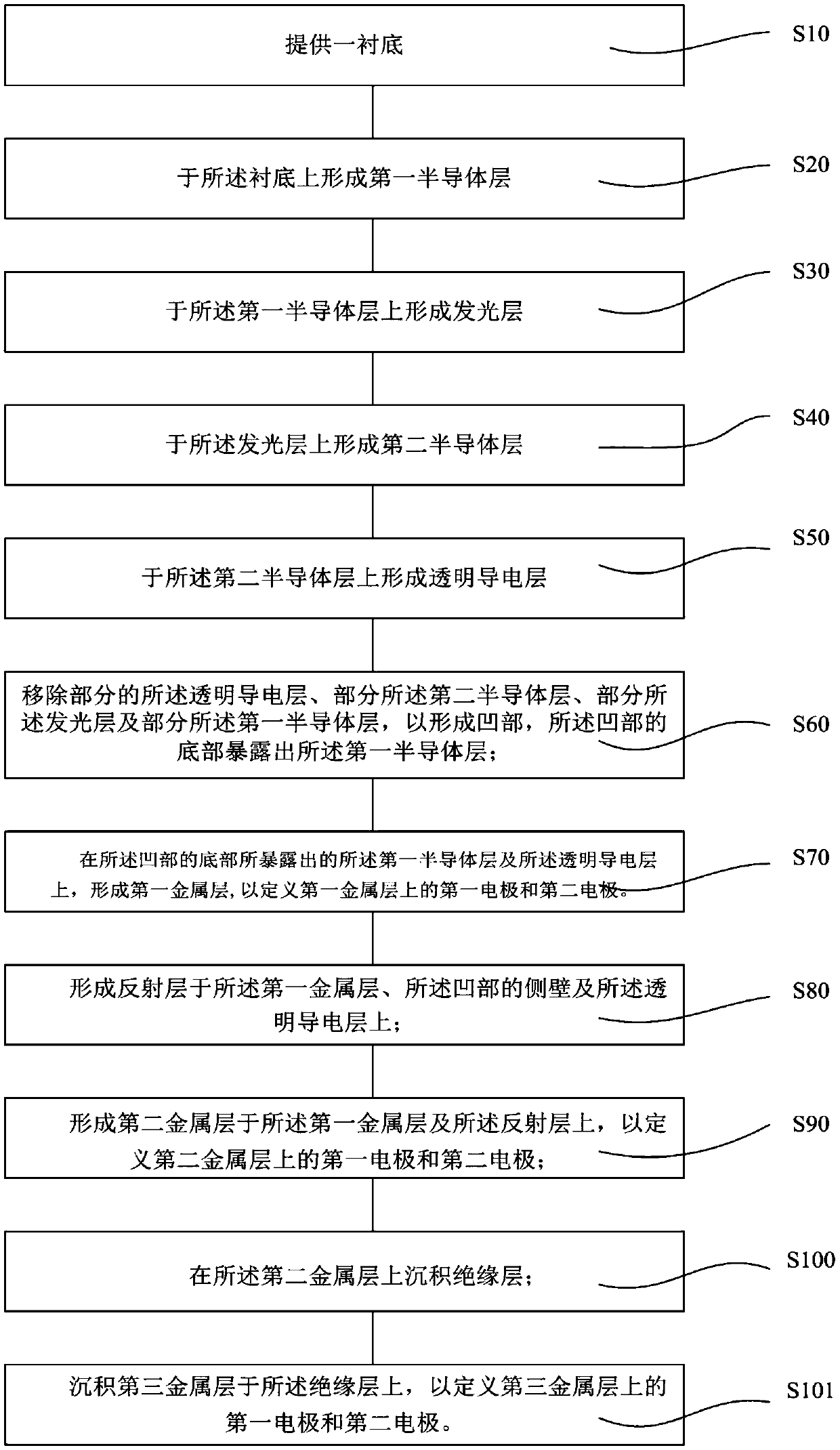
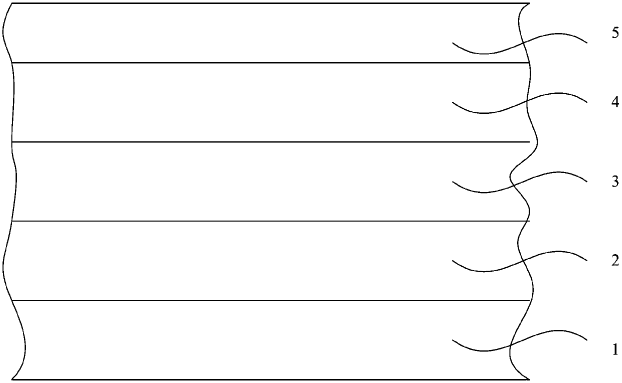
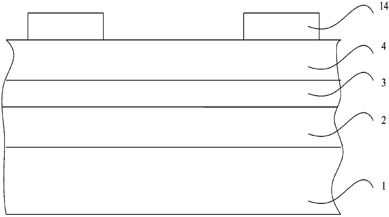
The invention provides a preparation method of a flip-over type light emitting diode chip. The preparation method comprises the steps of: providing a substrate and forming a first semiconductor layer,a light emitting layer, a second semiconductor layer and a transparent conducting layer on the substrate in sequence; removing a part of the transparent conducting layer, the second semiconductor layer, the light emitting layer and the first semiconductor layer to form a concave part, wherein the bottom of the concave part is exposed from the first semiconductor layer; forming first metal layerson the first semiconductor layer, from which the bottom of the concave part is exposed, and the transparent conducting layer so as to define first electrodes and second electrodes of the first metal layers; forming reflection layers on the first metal layers, the side wall of the concave part and the transparent conducting layer; forming second metal layers on the first metal layers and the reflection layers so as to define first electrodes and second electrodes of the second metal layers; depositing insulating layers on the second metal layers; and depositing third metal layers on the insulating layers so as to define first electrodes and second electrodes of the third metal layers. The chip prepared by the method is high in product yield.

Description

technical field [0001] The invention relates to the technical field of semiconductors, in particular to a method for preparing flip-chip light-emitting diode chips. Background technique [0002] In recent years, with the continuous expansion of the upstream industry, the light-emitting diode packaging industry has entered the era of meager profits. The fierce price competition and disorderly industry ecological chain have prompted the industry to demand new packaging technology, so the flip-chip light-emitting diode chip has taken advantage of the trend out. Compared with the front-mounted light-emitting diode chip, the flip-chip (Flip-chip) improves the luminous efficiency and improves the heat dissipation performance by avoiding the occupation of the light-emitting area by the electrodes in the front-mounted chip. At the same time, it also has low voltage, high brightness, high Reliability, high saturation current density and other advantages; in addition, the protection ...

Claims


Application Information

Patent Timeline
Patent Type & Authority Applications(China)
IPC IPC(8): H01L33/14H01L33/32H01L33/38H01L33/46H01L33/00
Inventor 唐驰刘亚柱吕振兴吴化胜操娟
Owner 合肥彩虹蓝光科技有限公司
Learn More