A high-speed railway catenary CT power-taking device and method

A power-taking device and high-speed railway technology, which is applied in the direction of circuit devices, battery circuit devices, collectors, etc., can solve the problems of extra-large current impact, short effective power-taking time, large loop current change range, etc., to achieve convenient engineering selection, Effects of improving charging efficiency, simplifying structure and control

Active Publication Date: 2022-05-31
WUHAN MARINE ELECTRIC PROPULSION RES INST CHINA SHIPBUILDING IND CORP NO 712 INST
View PDF5 Cites 0 Cited by
  • Summary
  • Abstract
  • Description
  • Claims
  • Application Information

AI Technical Summary

Problems solved by technology

[0009] To sum up, the CT power-taking device on the high-speed railway catenary has a short effective power-taking time, and the loop current varies greatly, which is vulnerable to the impact of extra-large current. The existing CT power-taking devices on the market cannot be used for online monitoring of the catenary. The device provides a stable and reliable low voltage power supply

Method used


Image

  • A high-speed railway catenary CT power-taking device and method
  • A high-speed railway catenary CT power-taking device and method
  • A high-speed railway catenary CT power-taking device and method

Examples


Embodiment Construction

[0046] The present invention will be further described below in conjunction with the accompanying drawings.

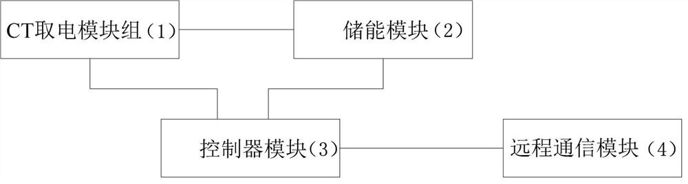
[0047] like Figure 1 to Figure 4 As shown, the present invention discloses a high-speed railway catenary CT power take-off device, which includes a CT power take-off module group 1 , an energy storage module 2 , a controller module 3 and a remote communication module 4 .

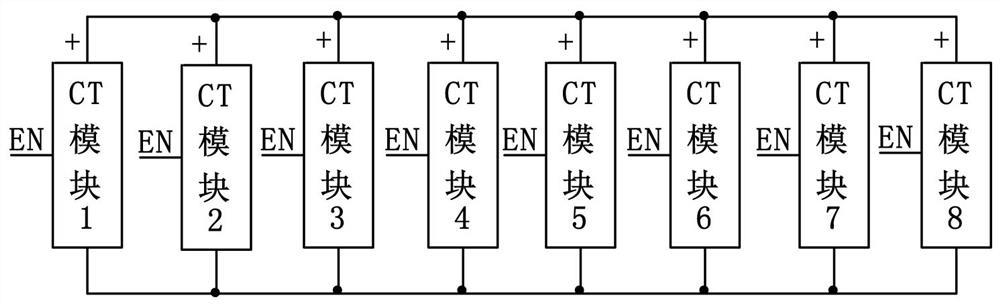
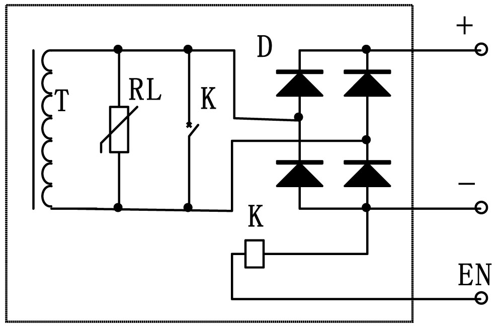
[0048] The CT power taking module group 1 is formed by connecting 8 CT modules, each CT module has 3 output terminals, which are the output positive "+", the output negative "-" and the power discharge enable " EN", the output terminals of each CT module are connected in parallel to the charging terminals "IN+" and "IN-" of the energy storage module 2, and the I / O ports of the controller module 3 are respectively connected to the power discharge enabling terminal "EN" of each CT module , the I / O ports of the controller module 3 are respectively connected to the relay coil control terminals "J1EN" a...


PUM


Abstract

The invention discloses a high-speed railway catenary CT power-taking device and method, comprising a CT power-taking module group, an energy storage module, a controller module and a remote communication module; the CT power-taking module group is connected by a plurality of CT modules. The output terminals of each module are connected in parallel to the input terminals of the energy storage module, and the controller module is respectively connected to the CT module group, the energy storage module and the remote communication module; the controller module controls the on-off of the electric energy discharge port of the CT module, adjust The power taken by the CT power module group; the controller module controls the switch of the energy storage module to charge and discharge the two battery groups in turn; the controller module starts the remote communication module to alarm when the device fails.

Description

technical field [0001] The invention belongs to the technical field of special power supplies, and in particular relates to a power supply device utilizing alternating current CT of a high-speed railway catenary to obtain power, which provides a stable and reliable power supply for on-line detection equipment on the high-speed railway catenary. Background technique [0002] The distribution of high-speed railways in my country is getting wider and wider. The catenary is one of the core technologies of the high-speed railway, but it is exposed to the natural environment and is easily affected by the environment. A stable and reliable low-voltage power supply is required for the online monitoring equipment of the catenary. CT (Current Transformer for short) takes electricity, including the electromagnetic core and the coil T wound on the electromagnetic core. The catenary line passes through the electromagnetic core. When alternating current passes through the catenary line, th...

Claims


Application Information

Patent Timeline
Patent Type & Authority Patents(China)
IPC IPC(8): H02J5/00H02J7/34H02J50/10
CPCH02J5/005
Inventor 陈世昌汪洋张志华张明武余俊
Owner WUHAN MARINE ELECTRIC PROPULSION RES INST CHINA SHIPBUILDING IND CORP NO 712 INST
Why Eureka
Try Eureka