
A Method for Realizing Near Field Focusing in Microwave Wireless Power Transmission System

A microwave radio and transmission system technology, applied in the direction of circuit devices, electrical components, etc., can solve the problems of inaccurate orientation and inability to realize high-power microwave energy transmission, and achieve the effect of precise orientation and high energy transmission efficiency

Active Publication Date: 2022-05-13
NANJING UNIV OF AERONAUTICS & ASTRONAUTICS
View PDF6 Cites 0 Cited by
  • Summary
  • Abstract
  • Description
  • Claims
  • Application Information

AI Technical Summary

Problems solved by technology

The directional radiation of the far field can be realized by using the phased array control method, but because the electromagnetic wave is in the far field state, the energy loss is proportional to the square of the distance, and high-power microwave energy transmission cannot be realized
In the far-field area, the electromagnetic wave is similar to a plane wave, which leads to the same angle and distance between the focal point and the antenna array element. The existing microwave wireless power transmission near-field focusing still adopts the plane wave condition, so there are more electromagnetic waves in the near field. dot, wrong orientation
When the distance between the antenna element and the focus point is different, the influence of the distance difference needs to be considered, so as to overcome the defect of inaccurate orientation

Method used

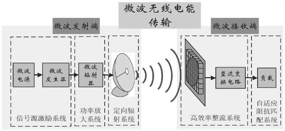
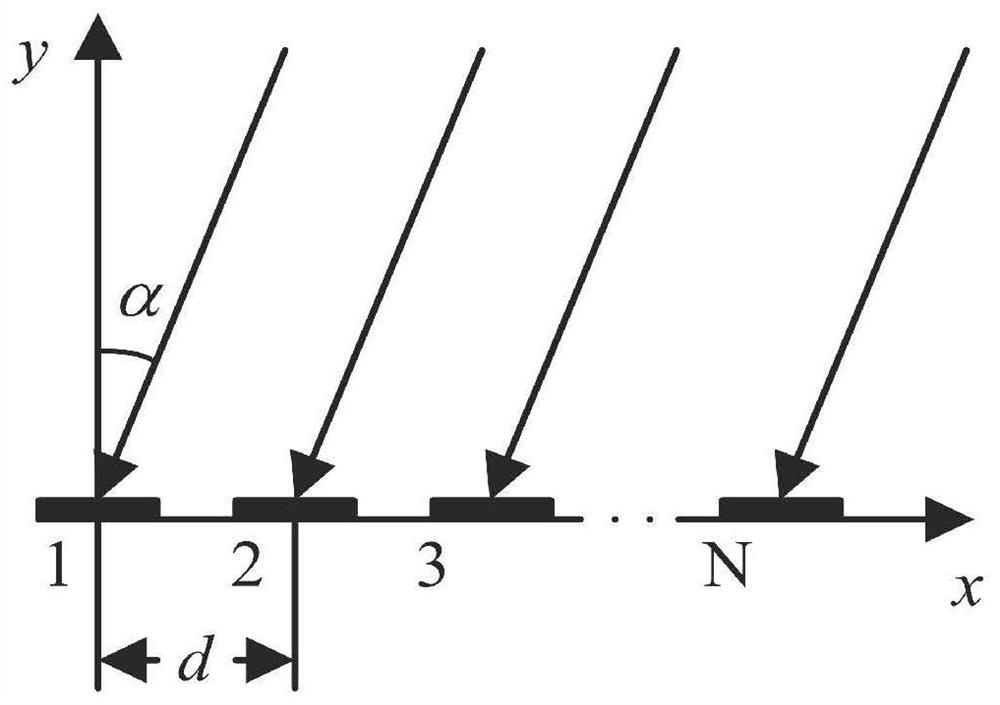

Image

  • A Method for Realizing Near Field Focusing in Microwave Wireless Power Transmission System
  • A Method for Realizing Near Field Focusing in Microwave Wireless Power Transmission System
  • A Method for Realizing Near Field Focusing in Microwave Wireless Power Transmission System

Examples


Embodiment Construction

[0022] The technical solution of the invention will be described in detail below in conjunction with the accompanying drawings.

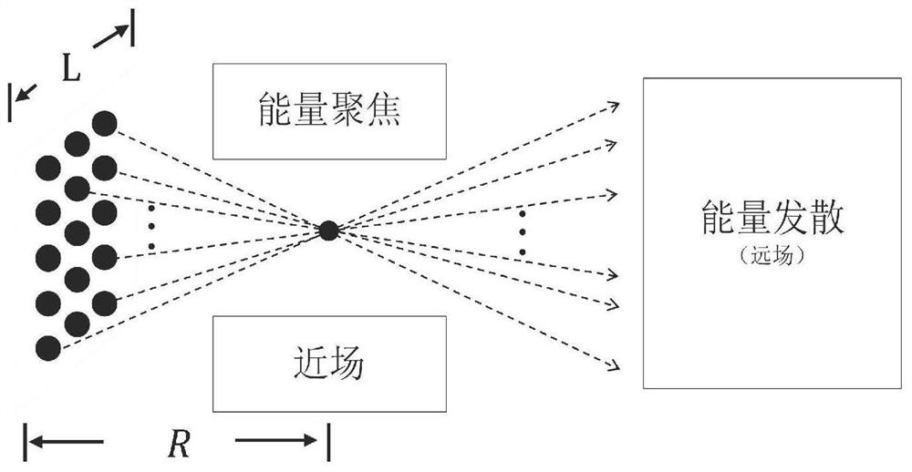
[0023] figure 2 It is a schematic diagram of the near-far field, and the near-far field demarcation point shown in formula (1) can be calculated according to the antenna array and the microwave frequency:

[0024]

[0025] R: is the near-far field dividing point;

[0026] L: the maximum size of the antenna array;

[0027] λ: microwave wavelength;

[0028] The electromagnetic wave in the far field is similar to a plane wave. Therefore, the distance difference between the focal point and each antenna element is fixed, but in the near field, that is, within the range of R, the electromagnetic wave is focused, and the focal point is in the same distance as each antenna. The distance between array elements is different. For microwaves with centimeter-level wavelengths, the distance between antenna elements and the distance between the focal point...


PUM


Abstract

The invention discloses a method for realizing near-field focusing in a microwave wireless energy transmission system, relates to microwave wireless energy transmission directional radiation technology, and belongs to the technical field of basic electrical components. This method firstly determines the near-field position of the focal point in the microwave wireless energy transmission, and deduces the spatial phase difference of adjacent array elements in the focused state, the distance between the focal point and the array, and the direction of the array element focusing The phase difference of the excitation current of adjacent array elements is calculated from the relationship between the point radiation beam direction, and the influence of the distance difference between the array element and the focus point on the orientation accuracy is considered, which can realize the directional radiation when focusing in the near field, which is a great support for future high-power The high-efficiency microwave wireless energy transmission system lays the foundation for directional radiation.

Description

technical field [0001] The invention discloses a method for realizing near-field focusing in a microwave wireless energy transmission system, relates to microwave wireless energy transmission directional radiation technology, and belongs to the technical field of basic electrical components. Background technique [0002] At present, there are four main implementation methods of wireless power transmission technology: electromagnetic induction, electromagnetic resonance, laser and microwave. Electromagnetic induction and electromagnetic resonance have high transmission power and high efficiency, but the transmission distance is short, which limits the application of this technology in the field of long-distance transmission. Laser type and microwave type are suitable for long-distance and high-power electric energy transmission occasions. The laser type has the advantages of good transmission orientation and small equipment volume, but the laser is easily affected by the env...

Claims


Application Information

Patent Timeline
Patent Type & Authority Patents(China)
IPC IPC(8): H02J50/20
CPCH02J50/20
Inventor 金科朱熹睿惠琦
Owner NANJING UNIV OF AERONAUTICS & ASTRONAUTICS
Learn More