Electric-powered car charging pile for solar power generating device

A power generation equipment and electric drive technology, which is applied in the field of new energy vehicle equipment, can solve the problems of vertical light emitting surface, unfavorable luminous efficiency, and small effective light emitting area, so as to ensure the power generation area, avoid excessive influence, and improve the service life.

Inactive Publication Date: 2019-04-16
LIAONING LIZHOU ENERGY TECH CO LTD
View PDF4 Cites 2 Cited by
  • Summary
  • Abstract
  • Description
  • Claims
  • Application Information

AI Technical Summary

Problems solved by technology

[0004] In order to solve the above problems, the existing patent publication number CN204243801U discloses a charging pile, but this charging pile cannot make the light-emitting surface perpendicular to the light as much as possible, resulting in a small effective light-emitting area, which is not conducive to improving the luminous efficiency.

Method used


Image

  • Electric-powered car charging pile for solar power generating device
  • Electric-powered car charging pile for solar power generating device
  • Electric-powered car charging pile for solar power generating device

Examples


Embodiment 1

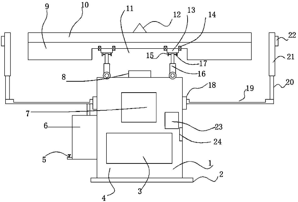
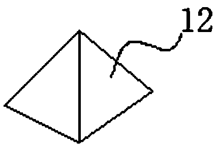
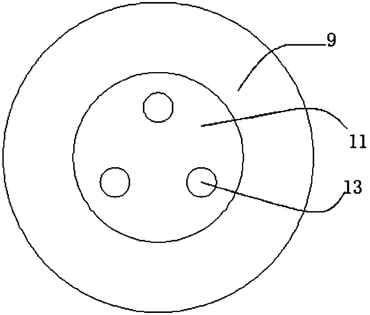
[0021] see Figure 1~3 , in an embodiment of the present invention, a charging pile for electric-driven vehicles of solar power generation equipment includes a main body 1, a base 2 is provided at the lower end of the box 1, a battery 3 is placed on the base 2, and the output end of the battery 3 is electrically connected to A transformer 23, the transformer 23 is electrically connected to the charging port 24, the charging port 24 is electrically connected to the operation panel 7 for controlling charging, the battery 3 is electrically connected to the junction box 8 on the top of the main body 1, the A mounting plate 9 is provided above the body 1, and a photovoltaic power generation panel 10 is installed on the mounting plate 9. The output terminal of the photovoltaic power generation plate 10 is connected to the input interface of the junction box 8, and a utility is provided between the mounting plate 9 and the top of the body 1. An adjustment mechanism for adjusting the ...

Embodiment 2

[0024] The difference from Embodiment 1 is: the outer side of the body 1 is provided with a mounting ring 18, and the outer side of the mounting ring 18 is provided with a positioning plate 19, the positioning plate 19 is a ring-shaped plate, and the upper surface of the positioning plate 19 is provided with a collecting groove. The outer side of the positioning plate 19 is connected with an enclosure 21 through a vertical bar 20, and an adjustment gap is provided between the enclosure and the mounting plate 9 to facilitate the adjustment of the adjustment mechanism. The vertical projection of the mounting plate 9 falls on the positioning plate 19, The collecting groove is provided with a water leakage port, and the water leakage hole is connected to the water storage tank 6 on the left side of the body 1 through a water diversion pipe. Rainwater will fall on the positioning plate 19, and then enter the water storage tank 6, so that the car can be cleaned temporarily, so as to ...


PUM


Abstract

The invention discloses an electric-powered car charging pile for a solar power generating device, which comprises a body. The lower end of a box body is provided with a base; a battery is arranged onthe base; the output end of the battery is electrically connected with a transformer; the transformer is electrically connected with a charging port; the charging port is electrically connected withan operation panel for controlling charging; and the battery is electrically connected with a wiring box located at the top part of the body. An improvement is made according to the shortcomings of the existing device. Through arranging an adjusting mechanism, a power generation plate is arranged vertically to light, and the effective power generation area of the device can be effectively ensured.A rainwater collection function is equipped, thereby playing a role of saving water. In addition, a fence is arranged, a role of blocking wind can be played, the adjusting mechanism can be preventedfrom being much influenced by the wind speed, and the service life of the device is improved.

Description

technical field [0001] The invention relates to the technical field of new energy vehicle equipment, in particular to a charging pile for electric-driven vehicles of solar power generation equipment. Background technique [0002] New energy vehicles refer to the use of unconventional vehicle fuels as power sources (or the use of conventional vehicle fuels and new vehicle power devices), and the comprehensive vehicle power control and advanced technology in driving, the formation of advanced technical principles, with Automobiles with new technology and new structure. [0003] The only disadvantage of electric vehicles is that they often need to be charged. How to charge electric vehicles is an important issue. Charging piles can effectively solve the problem of charging difficulties. Charging piles can quickly charge electric vehicles. Charging piles can be divided into AC charging piles and There are two types of DC charging piles. The AC charging pile is installed outsid...

Claims


Application Information

Patent Timeline
Patent Type & Authority Applications(China)
IPC IPC(8): H02S20/30H02J7/35H02S40/10F24S30/425B60L53/31B60L53/30B60L53/51
CPCH02J7/35H02S20/30H02S40/10Y02E10/50Y02T10/70Y02T10/7072Y02T90/12
Inventor 李哲
Owner LIAONING LIZHOU ENERGY TECH CO LTD
Why Eureka
Try Eureka