A multi-channel arbitrary base phase encoding signal optical generation device and generation method

A phase-encoded signal and generation device technology, applied in the field of microwave photonics, can solve the problems of stability influence, narrow bandwidth of pulse bandwidth-limited filters, and inability to simultaneously generate multiple phase-encoded microwave signals, etc.

Active Publication Date: 2021-07-06
GUANGDONG UNIV OF TECH
View PDF5 Cites 0 Cited by
  • Summary
  • Abstract
  • Description
  • Claims
  • Application Information

AI Technical Summary

Problems solved by technology

Related literatures have reported the use of microwave photonic time-delay filters to cause phase shifts, but the pulse bandwidth generated by this technique is limited by the narrow bandwidth of the filter
Phase-encoded microwave signals can also be generated based on the Sagnac interference ring structure, but the stability of the result is affected by small changes in the ring length
In order to solve the above problems, a single-output phase-encoded microwave signal method based on a single polarization modulator and dual parallel Mach-Zehnder modulators was proposed. Although the phase-encoded microwave signal generated by this method can be tuned in a wide range of frequencies, it cannot Simultaneous generation of multiple phase-encoded microwave signals

Method used


Image

  • A multi-channel arbitrary base phase encoding signal optical generation device and generation method
  • A multi-channel arbitrary base phase encoding signal optical generation device and generation method
  • A multi-channel arbitrary base phase encoding signal optical generation device and generation method

Examples


Embodiment Construction

[0058] The following will clearly and completely describe the technical solutions in the embodiments of the present invention with reference to the accompanying drawings in the embodiments of the present invention. Obviously, the described embodiments are only some, not all, embodiments of the present invention. Based on the embodiments of the present invention, all other embodiments obtained by persons of ordinary skill in the art without making creative efforts belong to the protection scope of the present invention.

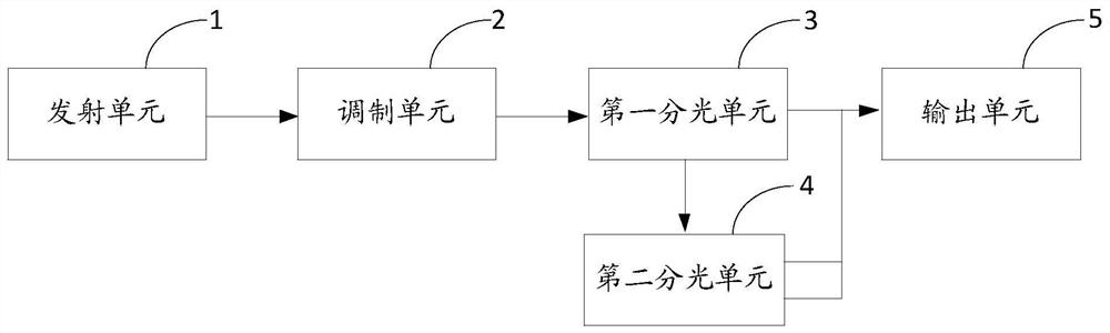
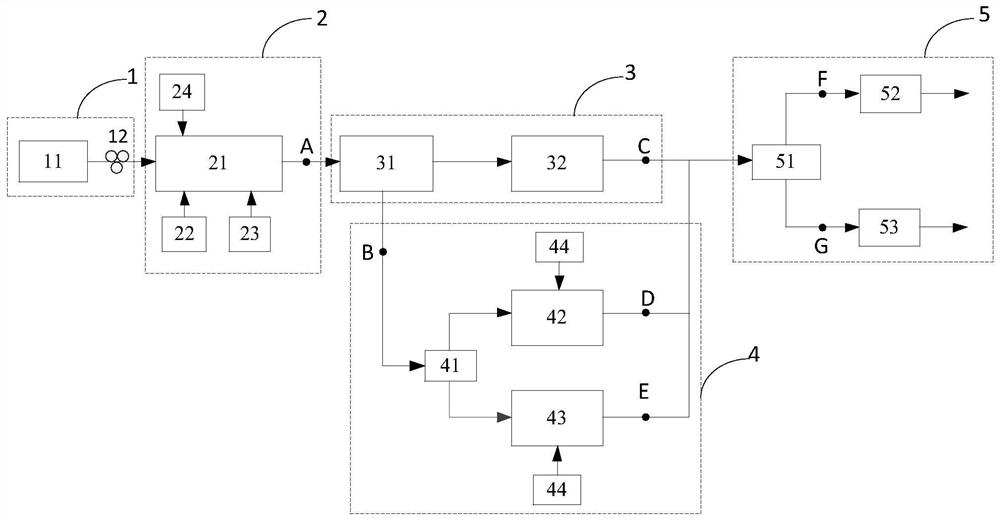
[0059] The present invention provides a multi-channel arbitrary base phase encoding signal optical generation device, such as figure 1 As shown, it includes: a transmitting unit 1, a modulating unit 2, a first light splitting unit 3, a second light splitting unit 4 and an output unit 5; wherein,

[0060] The transmitting unit 1 is used to generate an optical signal with a certain polarization direction;

[0061] The input terminal of the modulation unit 2 is ...


PUM


Abstract

This application discloses an optical generation device and method for multi-channel arbitrary phase encoding signals, including: a transmitting unit generates an optical signal with a certain polarization direction; The optical signal is modulated to generate positive and negative second-order sidebands with orthogonal polarization; the first light splitting unit divides the positive and negative second-order sidebands generated by the modulation unit into two paths of positive and negative second-order sidebands with orthogonal polarization respectively; the second light splitter unit The positive and negative second-order sidebands output by the first output end of the first optical splitting unit are separated, and then the encoded signals of any base are respectively loaded, and then the optical signal is output; the output unit outputs the first optical splitting unit and the second optical splitting unit After the optical signal is coupled, it is divided into two channels for photoelectric conversion, and two channels of arbitrary phase-encoded microwave signals are output at the same time. The application can improve the system transmission capacity and spectrum utilization rate, and the generated signal has the advantages of wide-range adjustable frequency, low noise, and large pulse compression ratio.

Description

technical field [0001] The invention relates to the technical field of microwave photonics, in particular to an optical generation device and method for multi-channel arbitrary phase encoding signals. Background technique [0002] Microwave pulse signals with large time-bandwidth products are widely used in modern radars. In order to make the pulse have a large time-bandwidth product, the radar transmitter usually performs phase encoding or frequency chirping on the microwave pulse, so that the pulse can be compressed by a matched filter at the radar receiver to achieve a high compression ratio, thereby improving radar accuracy. The method of using electronic circuits to generate phase-encoded or frequency-chirped pulses is very mature, but due to the limitation of "electronic bottleneck", the pulse time-bandwidth product generated by this method can no longer meet the high-precision and high-sensitivity requirements of modern radar systems. At present, a good solution is t...

Claims


Application Information

Patent Timeline
Patent Type & Authority Patents(China)
IPC IPC(8): H04B10/548H04B10/516H04B10/556
CPCH04B10/516H04B10/548H04B10/5561
Inventor 付晨远韩一石赵蓓丝郑俊文雷珂谢胜超
Owner GUANGDONG UNIV OF TECH
Why Eureka
Try Eureka