

Lens barrel
A lens barrel and lens technology, which is applied to instruments, installations, optics, etc., can solve problems such as performance deviation and assembly tolerance of lens barrels, and achieve the effect of suppressing manufacturing cost and low cost.
- Summary
- Abstract
- Description
- Claims
- Application Information
AI Technical Summary
Problems solved by technology
Method used
Image

Examples
Embodiment approach 1
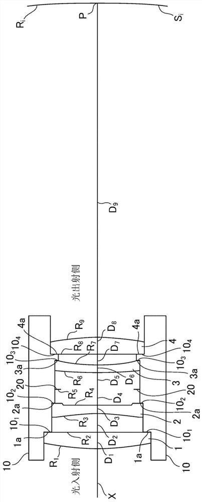
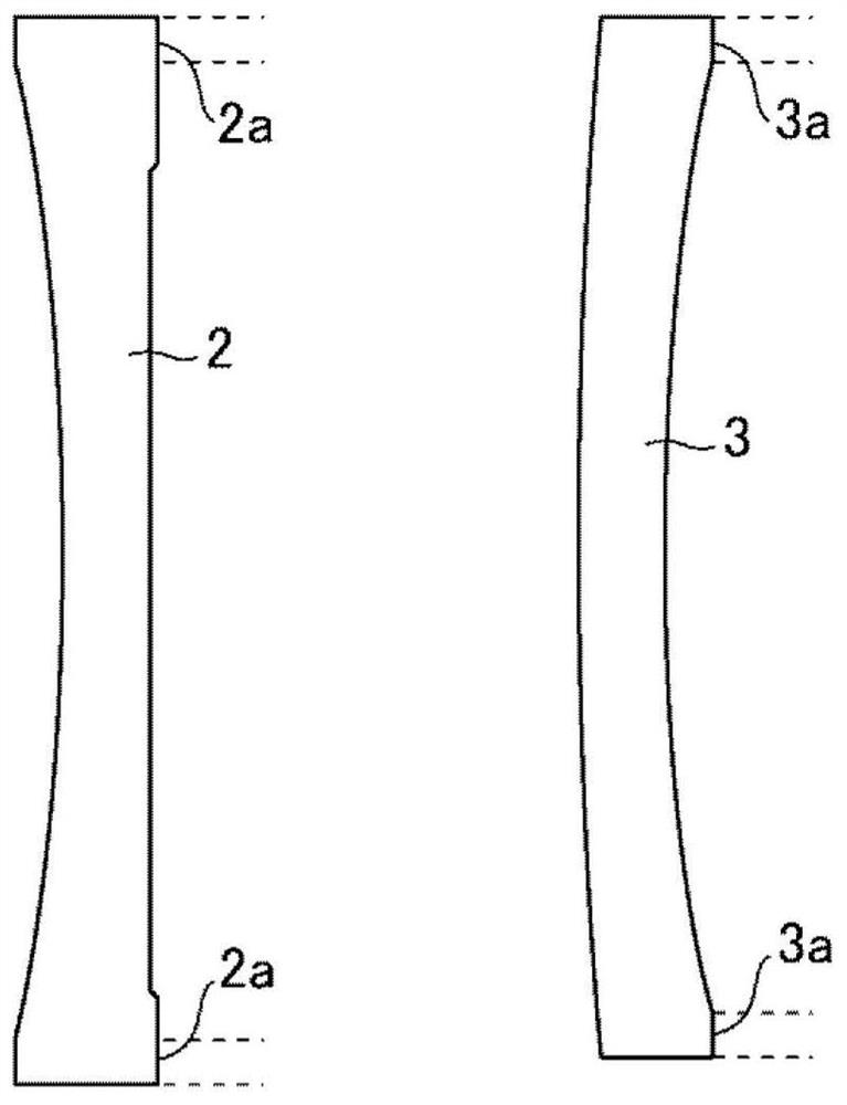
[0025] figure 1 It is a configuration diagram showing a lens barrel according to Embodiment 1 of the present invention, figure 2 It is an enlarged view showing the biconcave lens 2 and the meniscus lens 3 of the lens barrel according to Embodiment 1 of the present invention.
[0026] exist figure 1 and figure 2 Among them, the lens barrel 10 is a lens holding member that holds a plano-convex lens 1 (first lens), a biconcave lens 2 (second lens), a meniscus lens 3 (third lens), and a plano-convex lens 4 (fourth lens). The lens receiving surface has lens receiving surface 10 in order from the light incident side 1 (1st lens receiving surface), lens receiving surface 10 2 (2nd lens receiving surface), lens receiving surface 10 3 (3rd lens receiving surface), lens receiving surface 10 4 (4th lens receiving surface).
[0027] The surface of the plano-convex lens 1 on the light incident side is a convex surface, and the surface on the light exit side is a plane, with positi...
Embodiment approach 2
[0093] In Embodiment 1 above, an example was shown in which the second lens is a biconcave lens 2 whose both surfaces are concave. An example of a single concave lens whose surface is flat will be described.
[0094] Figure 4 is a configuration diagram showing a lens barrel according to Embodiment 2 of the present invention, and Figure 4 in, with figure 1 The same reference numerals denote the same or corresponding parts, and therefore explanations thereof are omitted.
[0095] The surface on the light incident side of the 2nd lens, that is, the single concave lens 2' is a concave surface, and the surface on the light exit side is a plane with negative refractive power.
[0096] In addition, the surface of the single concave lens 2' on the light exit side has a flat peripheral portion 2a', and the peripheral portion 2a' is pressed against the lens receiving surface 10. 2 Keep the single concave lens 2' under the state.
[0097] Figure 5 Each surface and image plane S ...
Embodiment approach 3
[0117] In Embodiments 1 and 2 above, an example was shown in which the third lens is a meniscus lens 3 in which the surface on the light incident side is convex and the surface on the light exit side is concave. 3. An example in which the lens is a single concave lens in which the surface on the light incident side is flat and the surface on the light exit side is concave will be described.
[0118] Figure 6 is a configuration diagram showing a lens barrel according to Embodiment 3 of the present invention, in Figure 6 in, with Figure 4 The same reference numerals denote the same or corresponding parts, and therefore explanations thereof are omitted.
[0119] The surface on the light incident side of the 3rd lens, that is, the single concave lens 3' is a plane, and the surface on the light exit side is a concave surface with negative refractive power.
[0120] In addition, the surface of the single concave lens 3' on the light incident side has a flat peripheral portion ...
PUM
 Abstract
Description
Claims
Application Information