
Mining scraper conveyer driving control system

A scraper conveyor and control system technology, which is applied to conveyor control devices, conveyors, conveyor objects, etc., can solve the problems of easy generation of overvoltage, emission waves, easy to produce slippage, affecting operation, etc., to improve explosion-proof Performance and use safety performance, prolong service life and use efficiency, avoid the effect of energy waste

Inactive Publication Date: 2019-04-19
NORTH CHINA INST OF SCI & TECH
View PDF9 Cites 1 Cited by
  • Summary
  • Abstract
  • Description
  • Claims
  • Application Information

AI Technical Summary

Problems solved by technology

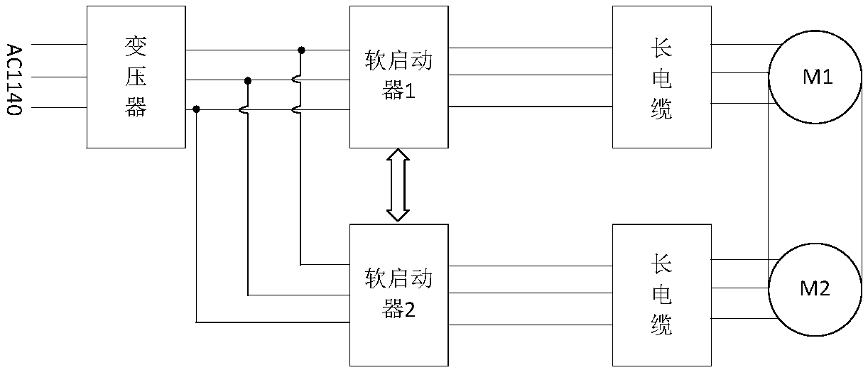
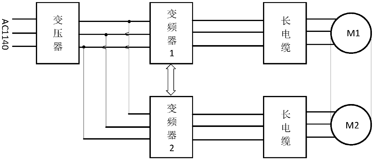
For the inverter on the output side of the scraper conveyor to supply power to the motor through a long cable, the output of the inverter is PWM wave and the long cable supplies power. The outstanding problems are: first, the harmonic reflection
At the same time, due to the existence of harmonics, when the inverter is powered by a long cable, the supply voltage and current are unstable, and the working conditions of the load cannot be effectively controlled.
Second, the inverter pulse reflection
However, there are many problems in this design method: (1) When there is a lot of raw coal on the scraper machine, the starting power torque becomes larger, requiring manual removal, and the efficiency is not high; (2) There is cable loss, and the mine working roadway is relatively long, requiring a long cables, resulting in a large tube voltage drop, insufficient starting voltage and operating voltage
(3) It is difficult to achieve synchronous control, which is not conducive to the actual production needs
(4) It will lead to waste of electric energy when no-load
(5) The belt is unevenly stressed, prone to slipping and other phenomena, and damages the motor of the conveyor
(1) The motor still cannot achieve synchronous control, which is easy to damage the scraper conveyor
(2) When there is a lot of raw coal on the transport plane, a power supply with more than 2.5 times the rated power of the motor is required for heavy-duty startup, which will cause the instability of the entire power grid and affect other operations
(3) It is easy to cause waste of electric energy when braking or idling
(4) The problem that the motor cannot start normally caused by uneven force is still not solved
(5) Long-distance control cannot be achieved, and short-distance control is still required, which is prone to safety accidents
(6) The electromagnetic interference of the two-level inverter governor is large, which affects the power grid
(7) The length of the connecting line between the scraper conveyor and the inverter varies from several hundred meters to 1000 meters, which is not conducive to the inverter supplying power to the long cable of the scraper conveyor, and it is easy to generate overvoltage, launch waves, and damage the motor and cables.
(8) When the power supply grid fluctuates, the output is unstable, which is likely to cause unnecessary failures

Method used


Image

  • Mining scraper conveyer driving control system
  • Mining scraper conveyer driving control system
  • Mining scraper conveyer driving control system

Examples


Embodiment Construction

[0025] The present invention will be further described below in conjunction with specific embodiments, and the advantages and characteristics of the present invention will become clearer along with the description. However, these embodiments are only exemplary and do not constitute any limitation to the scope of the present invention. Those skilled in the art should understand that the details and forms of the technical solutions of the present invention can be modified or replaced without departing from the spirit and scope of the present invention, but these modifications and replacements all fall within the protection scope of the present invention.

[0026] see image 3 , the present invention relates to a mining scraper conveyor drive control system, including two components control system, wherein one component control system is the main control system, the main control system is used to control the speed of the active motor M1 of the scraper conveyor, and the other One...


PUM


Abstract

The invention relates to a mining scraper conveyer driving control system. The mining scraper conveyer driving control system comprises two sets of branch control systems, wherein one set of branch control system is a main control system which is used for controlling the speed of a driving motor of a scraper conveyor, the other set of branch control system is a slave control system which is used for controlling the moment of a driven motor of the scraper conveyor, the two sets of systems are the main and slave control systems to each other, and each set of branch control system comprises a three-electrical-level PWM rectifier, a super-capacitor set, a three-electrical-level inverter and a wave filter which are connected together in sequence. The mining scraper conveyer driving control system has the advantages that an electric circuit is simple in structure, low in cost, easy to control and high in performance cost ratio, a power electronic technology and an all-digital intelligent technology are utilized, efficient utilization of the motors and electric energy thereof is realized, by means of organic combination with the super-capacitor sets, various special working conditions ofthe scraper conveyor can be realized more effectively, and effective utilization of regenerative energy is realized.

Description

technical field [0001] The invention relates to a driving control system of a mining scraper conveyor, which belongs to the control field of a mining scraper conveyor. By combining three-level PWM rectifiers, supercapacitor banks, and three-level inverters, heavy-duty starting, synchronous control, long cable operation control, and regenerative braking energy absorption and utilization of high-power mining scraper conveyors are realized. Background technique [0002] With the increase of mine production, the depth of mining is increasing and the cost of transportation is rising. At the same time, the traditional automobile transportation will produce a large amount of automobile exhaust, which seriously pollutes the underground environment. On the one hand, the use of tape transportation system can save a lot of transportation costs, on the other hand, it can reduce the emission of automobile exhaust and improve the environment of underground operations. Correspondingly, min...

Claims


Application Information

Patent Timeline
Patent Type & Authority Applications(China)
IPC IPC(8): B65G23/30B65G23/22B65G43/00B65G19/18
CPCB65G19/18B65G23/22B65G23/30B65G43/00B65G2203/0266
Inventor 邓永红张全柱孙英娟马红梅雷旻薛伟宁赵立永
Owner NORTH CHINA INST OF SCI & TECH
Learn More