
Laser machining method

A laser processing method and laser beam technology, applied in optics, opto-mechanical equipment, metal material coating process, etc., can solve problems such as the shape deviation of the opening part, and achieve the effect of reducing processing errors

Pending Publication Date: 2019-04-19
APS HLDG CORP
View PDF7 Cites 0 Cited by
  • Summary
  • Abstract
  • Description
  • Claims
  • Application Information

AI Technical Summary

Problems solved by technology

However, since oblique protrusions are generated on the surface on which the second etching is performed, this method can be adapted to the shape of the opening portion due to shadow generation due to the protrusions when depositing the organic material, or misalignment due to double-surface etching. Deviation

Method used


Image

  • Laser machining method
  • Laser machining method
  • Laser machining method

Examples


Embodiment Construction

[0041] Exemplary embodiments will be described in more detail hereinafter with reference to the accompanying drawings. This invention may, however, be embodied in different forms and should not be construed as limited to the embodiments set forth herein. Rather, these embodiments are provided so that this disclosure will be thorough and complete, and will fully convey the scope of the invention to those skilled in the art. In the embodiments, the same reference numerals refer to the same configurations, the drawings may be partially enlarged in order to clearly illustrate the exemplary embodiments, and the same reference numerals refer to the same elements in the drawings.

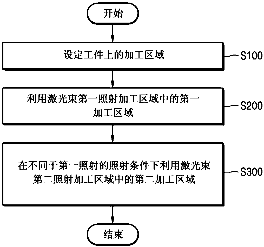
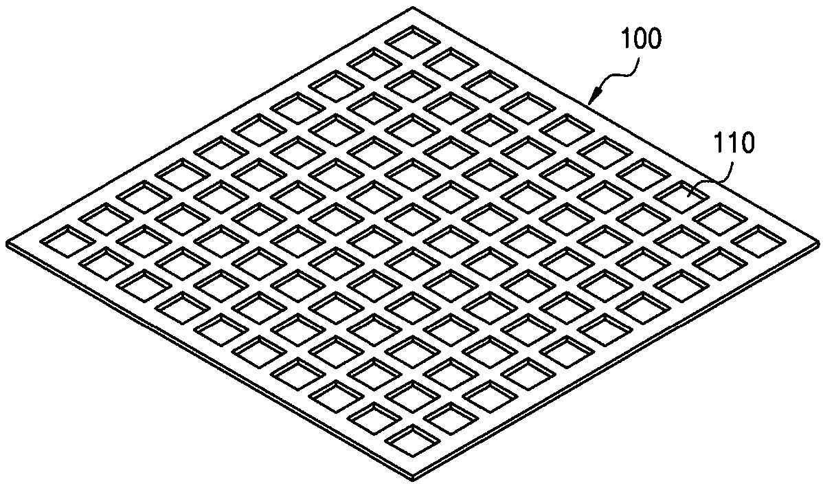
[0042] figure 1 is a flowchart illustrating a laser processing method according to an exemplary embodiment, and figure 2 is a perspective view showing a workpiece processed by the laser processing method according to the exemplary embodiment.

[0043] see figure 1 with figure 2 , the laser processin...


PUM


Abstract

A laser machining method according to an embodiment of the present invention includes the steps of setting a machining area on a workpiece; a step of firstly irradiating a laser beam onto a first machining area of the machining area of the workpiece; and a step of secondly irradiating the laser beam onto the second machining area of the machining area of the object to be processed with a differentirradiation condition from the first irradiation.

Description

technical field [0001] The present disclosure relates to a laser processing method, and more particularly to a laser processing method capable of reducing processing errors on a workpiece. Background technique [0002] When manufacturing an active matrix organic light-emitting diode (AMOLED), a vacuum deposition process is performed to deposit several organic material layers. In addition, different organic materials should be deposited separately for red, green, and blue (RGB) pixels. At this time, a fine metal mask (FMM) acts as a screen mask so that desired organic materials are deposited only to desired pixels, and organic materials are not deposited to other regions. [0003] Generally, when a fine metal mask is manufactured, holes are formed in the fine metal mask for depositing organic materials by a wet etching method. However, when the fine metal mask is manufactured by a wet etching method, the size of the fine metal mask and the accuracy of holes formed in the fi...

Claims


Application Information

Patent Timeline
IPC IPC(8): C23C14/04
CPCC23C14/042G03F7/2053H10K71/162H10K71/00
Inventor 成栋永朴锺甲金治宇
Owner APS HLDG CORP
Learn More