High pressure angle throttle valve

A throttle valve and angle-type technology, which is applied in the direction of sliding valves, valve details, valve devices, etc., can solve the problems of unstable flow control, inability to cut off the medium, and hidden dangers of well control safety, so as to avoid machining accuracy and installation The difficulty is too high, the effect of avoiding the accelerated erosion of the sealing ring line and reducing the requirements for grinding accuracy

Pending Publication Date: 2019-04-19
CHENGDU CHENGFENG VALVE +2
View PDF0 Cites 3 Cited by
  • Summary
  • Abstract
  • Description
  • Claims
  • Application Information

AI Technical Summary

Problems solved by technology

Most of the opening and closing parts of the traditional throttle valve are conical and streamlined. The valve stem drives the valve core to move up and down to change the cross-sectional area between the valve core and the valve seat to realize the flow control of the liquid. Since the medium is between the throttle valve core and the valve seat The flow rate is very high, especially in small gaps, the smaller the gap, the greater the flow rate, and it is easy to generate eddy currents (the so-called cavitation phenomenon), which has great erosion and wear on the valve core and valve seat, and is prone to vibration, resulting in flow loss. The control is not stable, and the connection between the valve core and the valve stem is easy to bend and break, which brings great safety hazards to well control
The adjustment accuracy of the traditional throttle valve is not high, the sealing surface is easy to be eroded, and the sealing performance is poor, so it cannot be used to cut off the medium

Method used


Image

  • High pressure angle throttle valve
  • High pressure angle throttle valve
  • High pressure angle throttle valve

Examples


Embodiment Construction

[0040] In order to make the object, technical solution and advantages of the present invention clearer, the present invention will be further described in detail below in conjunction with the accompanying drawings.

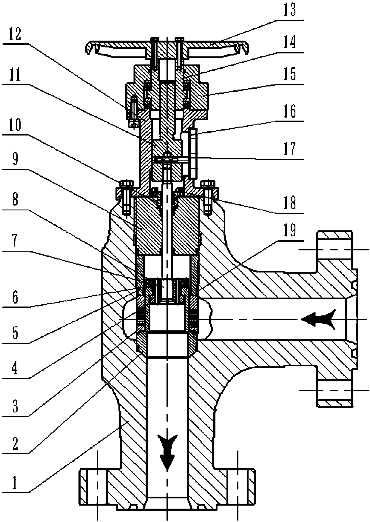
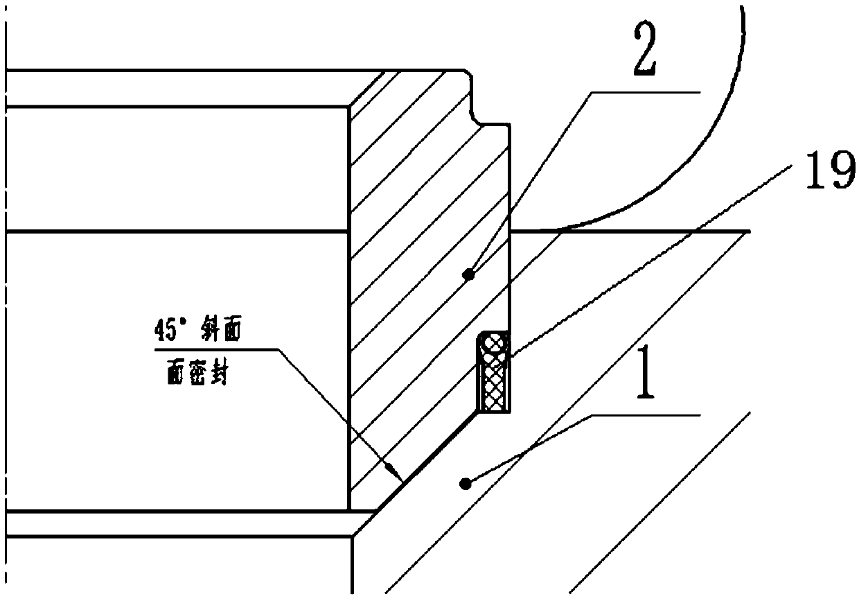
[0041] Such as figure 1 As shown, the high-pressure angle throttle valve disclosed by the present invention includes a valve stem 7, a valve core assembly, a valve seat 2, a sleeve 3, a coupling sleeve 11, a bracket 12, a hand wheel 13, a coupling sleeve nut 14, a shaft Sleeve 5, gland 9 and angle-shaped valve body 1, valve seat 2, sleeve 3, and shaft sleeve 5 are installed in valve body 1 in turn from bottom to top and pressed by gland 9. Gland 9 and valve body 1 screw connection.

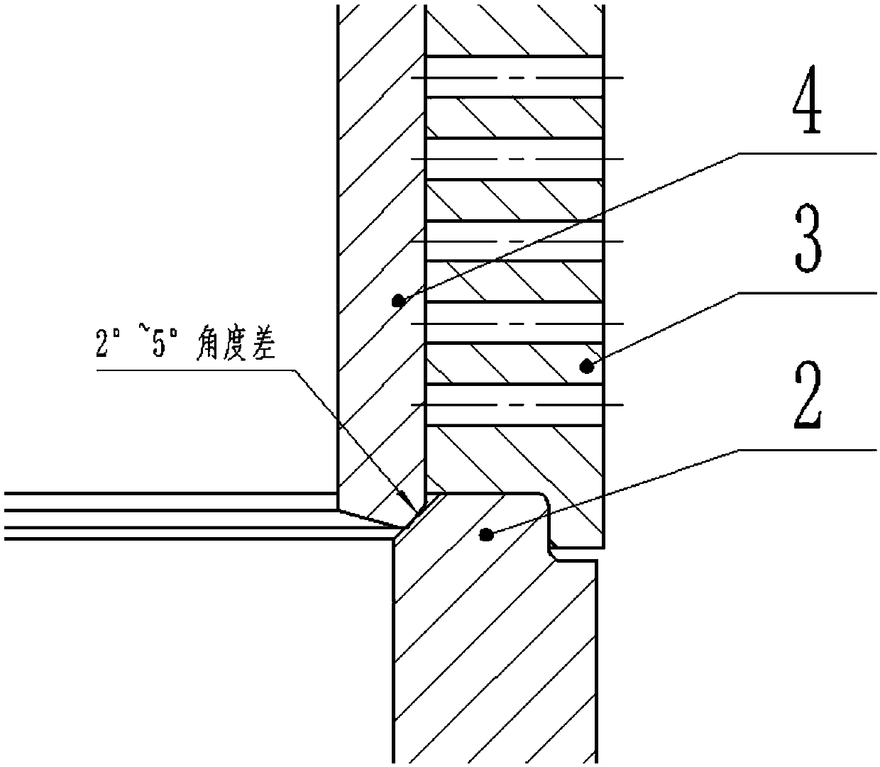
[0042] Such as figure 1 , 2 As shown, the sleeve 3 is provided with at least two longitudinal orifices in the circumferential direction, and at least some of the longitudinal orifices are staggered in the longitudinal direction; the lower end of the valve stem 7 extends into the va...


PUM


Abstract

The invention relates to a high pressure angle throttle valve which comprises a valve rod, a valve element assembly, a valve base, a sleeve and an angle valve body. The valve element assembly, the valve base and the sleeve are arranged in the valve body, the valve base is coaxially arranged below the sleeve, at least two longitudinal rows of throttle holes are annularly formed in the sleeve, at least part of throttle holes in part of longitudinal rows are staggered in the longitudinal direction, the lower end of the valve rod stretches into the valve body to be connected with the valve elementassembly, the number of the throttle holes to be opened is selected through up-down movement of the valve element assembly in the sleeve, sealing faces between a sealing shaft sleeve and the valve base have an angle difference of 2-5 degrees to form line seal, a coupling sleeve is in threaded connection with the valve rod, a plug pin prevents rotation, a pin hole of the valve rod is designed intoa U-shaped groove, therefore, the problem that pin hole machining precision and installation difficulty are too high is solved, and the valve rod can be moved up and down in the coupling sleeve to adjust the position. The high pressure angle throttle valve is reasonable in design, simple in structure, good in throttle effect, stable in performance, long in service life, safe, reliable, capable ofachieving high-precision adjustment and capable of cutting off media to close a fluid passage.

Description

technical field [0001] The invention relates to the technical field of valves, in particular to a high-pressure angle throttle valve. Background technique [0002] The throttle valve is the key equipment in the drilling well control manifold, which controls the fluid flow by changing the throttle cross-sectional area. Most of the opening and closing parts of the traditional throttle valve are conical and streamlined. The valve stem drives the valve core to move up and down to change the cross-sectional area between the valve core and the valve seat to realize the flow control of the liquid. Since the medium is between the throttle valve core and the valve seat The flow rate is very high, especially in small gaps, the smaller the gap, the greater the flow rate, and it is easy to generate eddy currents (the so-called cavitation phenomenon), which has great erosion and wear on the valve core and valve seat, and is prone to vibration, resulting in flow loss. The control is not ...

Claims


Application Information

Patent Timeline
Patent Type & Authority Applications(China)
IPC IPC(8): F16K3/24F16K3/314F16K39/04F16K3/30F16K41/02F16K37/00
CPCF16K3/246F16K3/30F16K3/314F16K37/0016F16K39/04F16K41/02
Inventor 曾品其林浩童俊曾和友王剑英杨建超关玉堂王新月刘子立
Owner CHENGDU CHENGFENG VALVE
Why Eureka
Try Eureka