Oil fume purifying integrated machine

An oil fume purification and all-in-one machine technology, which is applied in the field of range hoods, can solve problems such as inconvenient installation, large space occupation, troublesome maintenance, etc., and achieve the effect of convenient installation and reduced space occupation

Pending Publication Date: 2019-04-19
佛山市云厨环保科技有限公司
View PDF0 Cites 5 Cited by
  • Summary
  • Abstract
  • Description
  • Claims
  • Application Information

AI Technical Summary

Problems solved by technology

However, the range hood and the oil fume purification device are installed separately, and the two are connected by a smoke exhaust pipe, which has the disadvantages of taking up a lot of space, inconvenient installation, and troublesome maintenance.

Method used


Image

  • Oil fume purifying integrated machine
  • Oil fume purifying integrated machine
  • Oil fume purifying integrated machine

Examples


Embodiment 1

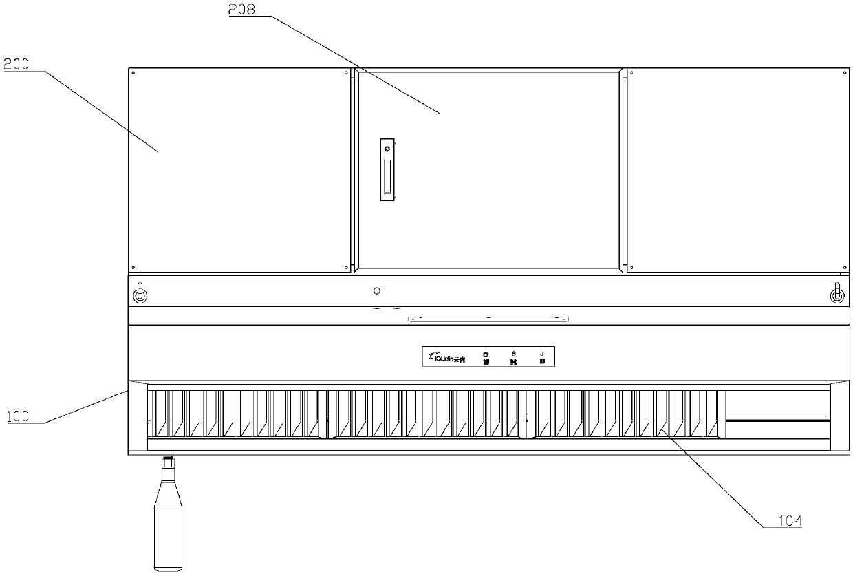
[0062] Such as figure 1 , figure 2 , image 3 , Figure 4 , Figure 5 , Image 6 with Figure 7 As shown, a lampblack purification integrated machine, which includes:

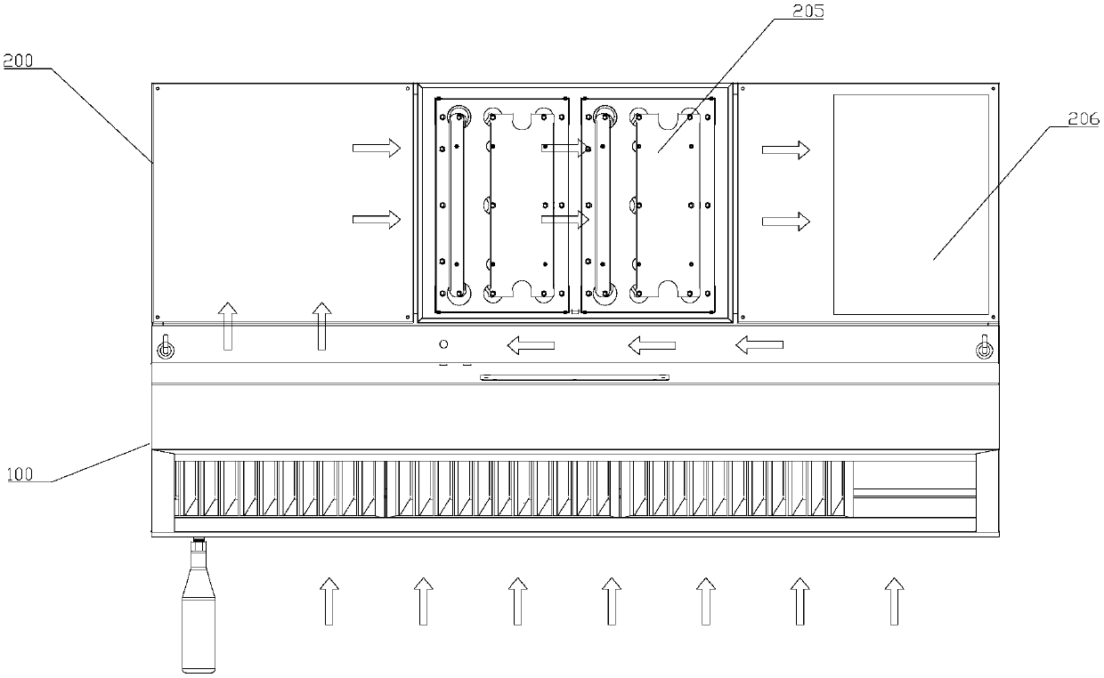
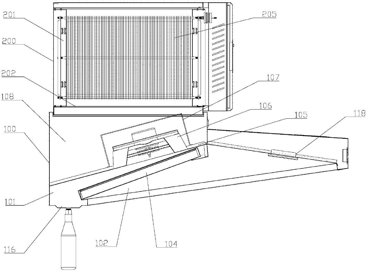
[0063] The oil fume collecting part 100 and the oil fume purifying part 200 arranged above the oil fume collecting part 100;

[0064] The oil fume collecting part 100 is provided with an oil fume processing chamber 101; the bottom of the oil fume processing chamber 101 is provided with a processing chamber inlet 102, and its upper part is provided with a processing chamber outlet 103;

[0065] The oil fume treatment chamber 101 is provided with an oil retaining mechanism 104 and an oil fume pretreatment mechanism 105 sequentially from bottom to top; the oil fume pretreatment mechanism 105 includes a plurality of oil fume separation assemblies 106 arranged side by side;

[0066] The oil fume purification unit 200 is provided with an oil fume purification chamber 201; the bottom of the oil fume purification...

Embodiment 2

[0085] The technical solution described in this embodiment is basically the same as that of Embodiment 1, the difference is that:

[0086] Such as Figure 8 , Figure 9 with Figure 10 As shown, the oil fume pretreatment mechanism 105 also includes an installation panel 108 arranged parallel to the bottom plate 202 of the clean chamber, and the installation panel 108 is provided with a plurality of installation holes 109 matching the oil fume separation assembly 106 . The installation panel is arranged parallel to the bottom plate 202 of the purification chamber, so that the oil fume separation assembly can fully contact with the oil fume, so as to better disperse large particles of oil fume.

[0087] Further, the windshield mechanism 107 includes: a windshield 110 matched with the oil fume separation assembly 106 and a plurality of connecting brackets 111 arranged at intervals;

[0088] The connection bracket 111 has a fixed end and an installation end, the fixed end is f...


PUM


Abstract

The invention discloses an oil fume purifying integrated machine. The oil fume purifying integrated machine comprises an oil fume collecting part and an oil fume purifying part, wherein an oil fume processing cavity is arranged in the oil fume collecting part; a processing cavity inlet is formed below the oil fume processing cavity, and a processing cavity outlet is formed above the oil fume processing cavity; an oil blocking mechanism and an oil fume pretreatment mechanism are sequentially arranged in the oil fume processing cavity from bottom to top; the oil fume pretreatment mechanism comprises a plurality of oil fume separation components; the oil fume purifying part is provided with a purifying cavity inlet located at the left end of an oil fume purifying cavity; a purifying cavity outlet is formed in the right end of the oil fume purifying cavity; an electric field module and a draught fan are arranged in the oil fume purifying cavity from left to right in sequence; an air inletof the draught fan directly faces the electric field module; an air outlet of the draught fan communicates with the purifying cavity outlet; the processing cavity outlet is connected to the purifyingcavity inlet, so that the oil fume processing cavity communicates with the oil fume purifying cavity; and an air blocking mechanism is arranged above the oil fume separation components located directly below the purifying cavity inlet. The oil fume purifying integrated machine improves the efficiency of oil fume purification, reduces the occupied space, and is convenient to install by adopting integrated setting.

Description

technical field [0001] The invention relates to the technical field of range hoods, in particular to an integrated range hood purification machine. Background technique [0002] The cooking process will produce a lot of soot. In order to reduce the damage of soot to people's health, the prior art generally installs a range hood above the stove, and quickly sucks away the exhaust gas generated by the stove combustion and the soot generated during the cooking process. Exhaust to the outside to reduce the harm of oil fume to indoor personnel. [0003] In order to better protect the environment, a fume purification device connected to the range hood is generally installed outside the range hood to purify the fume to be discharged outside. However, the range hood and the oil fume purification device are installed separately, and the two are connected by a smoke exhaust pipe, which has the disadvantages of taking up a lot of space, inconvenient installation, and troublesome maint...

Claims


Application Information

Patent Timeline
Patent Type & Authority Applications(China)
IPC IPC(8): F24C15/20
CPCF24C15/20
Inventor 潘勇员
Owner 佛山市云厨环保科技有限公司
Why Eureka
Try Eureka