A design method and device for a casing wellhead annulus pressure prevention tool
An annulus under pressure and casing technology, which is applied in design optimization/simulation, calculation, special data processing applications, etc., can solve the problems of little research progress and cannot meet the problem of wellhead annulus under pressure, and improve strain coordination ability, inhibiting gas well wellhead annulus pressure, and improving the effect of gas sealing ability
- Summary
- Abstract
- Description
- Claims
- Application Information
AI Technical Summary
Problems solved by technology
Method used
Image
Examples
Embodiment 1
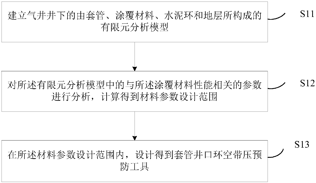
[0055] see figure 1 It is a schematic flowchart of a design method of a casing wellhead annulus prevention tool provided in Embodiment 1 of the present invention. The method includes the following steps:
[0056] S11. Establish a finite element analysis model composed of casing, coating material, cement sheath and formation in the downhole of the gas well;
[0057] Wherein, in the gas well, the coating material is located between the casing and the cement sheath, and the cement sheath is located between the coating material and the formation.
[0058] It should be noted that the main purpose of gas well cementing and cementing operations is to effectively isolate the casing outer annulus to prevent formation fluid channeling during gas well drilling, stimulation operations and production; and to form a complete cement sheath to effectively support and protective sleeve. During the drilling and development of gas wells, the cement sheath is subject to such effects as casing i...
Embodiment 2
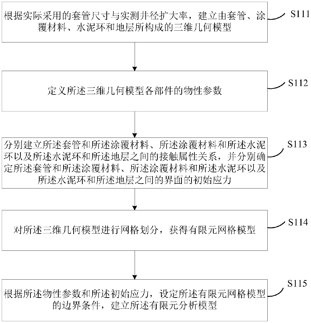
[0065] Referring to embodiment one of the present invention and figure 1 For the specific process of steps S11 to S13 described in , see figure 2 Corresponding to the second embodiment of the present invention figure 1 A schematic flow chart of establishing a finite element analysis model in the step S11 shown, specifically including:
[0066] S111. Establish a three-dimensional geometric model composed of casing, coating material, cement sheath and formation according to the casing size actually used and the measured borehole expansion ratio;
[0067] S112. Define physical parameters of each component of the three-dimensional geometric model;
[0068] Specifically, according to the actual downhole working conditions of on-site drilling, the physical property parameters and cement sheath failure criteria of each component in the established three-dimensional ensemble model are defined. Wherein, the coating material parameter range includes but is not limited to the effecti...
Embodiment 3
[0092] Corresponding to the design method of the casing wellhead annulus prevention tool disclosed in the first and second embodiments of the present invention, the third embodiment of the present invention also provides a design device for the casing wellhead annulus prevention tool, see Figure 5 It is a structural schematic diagram of a device for designing a casing wellhead annulus prevention tool provided in Embodiment 3 of the present invention, and the device includes:
[0093] Establishment module 1, used to establish a finite element analysis model composed of casing, coating material, cement sheath and formation in the downhole of the gas well, wherein, in the gas well, the coating material is located on the casing and the Between the cement sheath, the cement sheath is located between the coating material and the formation;
[0094] The calculation module 2 is used to analyze the parameters related to the performance of the coating material in the finite element an...
PUM
 Abstract
Description
Claims
Application Information
 - R&D
- Intellectual Property
- Life Sciences
- Materials
- Tech Scout
- Unparalleled Data Quality
- Higher Quality Content
- 60% Fewer Hallucinations
Browse by: Latest US Patents, China's latest patents, Technical Efficacy Thesaurus, Application Domain, Technology Topic, Popular Technical Reports.
© 2025 PatSnap. All rights reserved.Legal|Privacy policy|Modern Slavery Act Transparency Statement|Sitemap|About US| Contact US: help@patsnap.com


