Contact protection layer for conductive terminal and method for forming same

A conductive terminal and contact protection technology, which is applied in the field of contact protection layer, can solve problems affecting electrical contact performance, corrosion resistance and wear resistance, electrical contact failure of conductive terminals, corrosion of conductive terminals, etc., to improve corrosion resistance Performance, improvement of electrical conductivity, effect of reducing usage

Active Publication Date: 2021-03-09
TYCO ELECTRONICS (SHANGHAI) CO LTD
View PDF3 Cites 0 Cited by
  • Summary
  • Abstract
  • Description
  • Claims
  • Application Information

AI Technical Summary

Problems solved by technology

However, the reduction in the thickness of the noble metal layer on the conductive terminal will inevitably affect the electrical contact performance, corrosion resistance and wear resistance
Especially under severe environmental conditions, it can lead to corrosion and wear of the conductive terminals, which can lead to failure of the electrical contact of the conductive terminals

Method used


Image

  • Contact protection layer for conductive terminal and method for forming same
  • Contact protection layer for conductive terminal and method for forming same
  • Contact protection layer for conductive terminal and method for forming same

Examples


Embodiment Construction

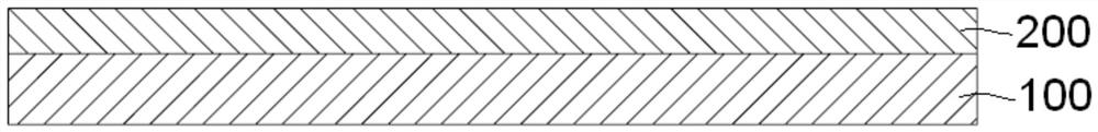
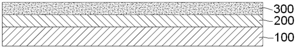
[0038] The technical solutions of the present invention will be further specifically described below through the embodiments and in conjunction with the accompanying drawings. In the specification, the same or similar reference numerals designate the same or similar components. The following description of the embodiments of the present invention with reference to the accompanying drawings is intended to explain the general inventive concept of the present invention, but should not be construed as a limitation of the present invention.

[0039] In addition, in the following detailed description, for purposes of explanation, numerous specific details are set forth in order to provide a comprehensive understanding of the embodiments of the present disclosure. It may be evident, however, that one or more embodiments may be practiced without these specific details. In other instances, well-known structures and devices are shown in diagrammatic form to simplify the drawings.

[0...


PUM


Abstract

The invention discloses a contact protection layer of a conductive terminal, comprising: a nickel layer formed on the outer surface of a base metal of the conductive terminal; and an anti-corrosion organic film formed on the outer surface of the nickel layer. A microporous structure distributed in a predetermined pattern is formed on the anti-corrosion organic film; and precious metal is filled in the micro-porous structure of the anti-corrosion organic film, thereby forming a noble metal microstructure on the outer surface of the nickel layer. In addition, the invention also discloses a method for forming the contact protection layer. In the present invention, a precious metal microstructure is formed on the contact of the conductive terminal instead of a noble metal layer, thereby reducing the amount of precious metal used and the manufacturing cost of the conductive terminal. At the same time, since the noble metal microstructure has good electrical conductivity, the electrical conductivity of the conductive terminal can be improved. Moreover, the rest of the contact of the conductive terminal not covered by the noble metal microstructure is covered with an anti-corrosion organic film, so that the anti-corrosion performance of the conductive terminal can be improved.

Description

technical field [0001] The invention relates to a contact protection layer of a conductive terminal and a method for forming the contact protection layer. Background technique [0002] Since the contact of the conductive terminal directly affects the electrical connection performance of the conductive terminal, it is desired that the contact of the conductive terminal has excellent conductive performance. Conductive terminals are usually made of copper, which has very good electrical conductivity, but copper has poor corrosion resistance and wear resistance. [0003] In order to effectively protect the contacts of the conductive terminals and prevent the contacts of the conductive terminals from being corroded and worn, in the prior art, it is usually necessary to plate a layer of noble metal, such as gold or silver, on the entire contact surface of the conductive terminals. Precious metals have excellent electrical conductivity, corrosion resistance and wear resistance. Th...

Claims


Application Information

Patent Timeline
Patent Type & Authority Patents(China)
IPC IPC(8): H01R13/03H01R13/02H01R43/16
CPCH01R13/02H01R13/03H01R43/16
Inventor 徐文忠周建坤刘劲松黄忠喜
Owner TYCO ELECTRONICS (SHANGHAI) CO LTD
Why Eureka
Try Eureka