Double-machine traction device

A traction and traction sheave technology is applied in the field of double-machine traction devices, which can solve the problems of insufficient braking force, low braking reliability, low elevator safety, etc., so as to avoid safety accidents and ensure reliable braking. Effect

Pending Publication Date: 2019-04-23
SHAANXI SIUSAI ELECTROMECHANICAL TECH CO LTD
View PDF1 Cites 1 Cited by
  • Summary
  • Abstract
  • Description
  • Claims
  • Application Information

AI Technical Summary

Problems solved by technology

[0007] The invention solves the defects that the existing elevator performs emergency braking through the brake, and the car cannot be braked quickly due to the insufficient holding force of the brake, the braking reliability is low, and the elevator safety is not high. It provides a A double-machine traction device, which can quickly brake when the elevator system fails, and directly locks and brakes through a traction wheel locking method. The braking reliability is high, and it can effectively prevent the car from jumping to the top or squatting. Bottom safety accident
[0008] The present invention also solves the defects that the existing elevator cannot save itself and needs an external professional rescue team to rescue, the waiting time in the car is long, and it is easy to lose the first rescue time. It provides a double-machine traction device with a rescue The motor can be rescued by passengers in the car, winning the first rescue time and improving the safety of the elevator

Method used


Image

  • Double-machine traction device
  • Double-machine traction device
  • Double-machine traction device

Examples


Embodiment 1

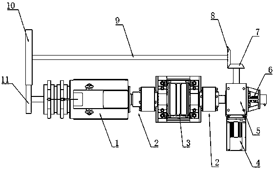
[0030] Embodiment 1: An elevator double machine traction device (see figure 1 ), including traction machine 1, traction wheel 3, worm gear mechanism 5, rescue motor 4 and synchronous mechanism.

[0031] The traction machine is arranged on the installation platform at the top of the elevator shaft. The traction machine in this embodiment adopts a servo motor. The servo motor can accurately control the speed, and the traction machine is used as the power source for the lifting of the car. The traction machine adopts a two-way transmission structure, the output of one end is coaxially connected with the traction wheel through the coupling 2, and the other end is connected with the synchronous mechanism. The other side of the traction sheave is connected with the worm gear mechanism through a coupling. A traction rope is wound around the traction sheave, one end of the traction rope is connected to the car after passing around the diverting pulley, and the other end of the tracti...

Embodiment 2

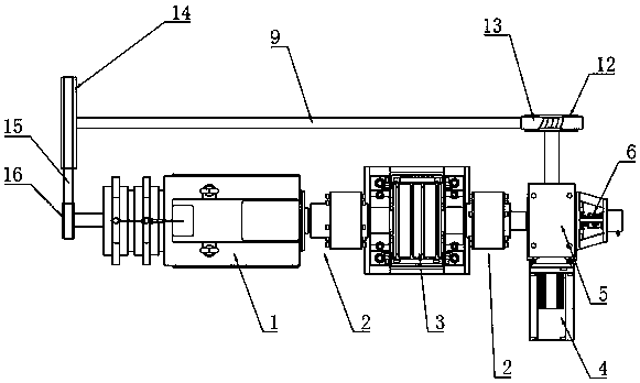
[0035] Embodiment 2: An elevator double machine traction device (see figure 2 ), including traction machine 1, traction wheel 3, worm gear mechanism 5, rescue motor 4 and synchronous mechanism.

[0036] The synchronous mechanism includes a transmission rod 9, which is parallel to the rotation axis of the traction wheel, and the transmission rod and the worm are connected through a transmission mechanism that can change the transmission direction by 90°. In this embodiment, the transmission mechanism that can change the transmission direction by 90° adopts a worm gear. The worm gear 12 is connected with the worm in the worm gear mechanism, and the worm 13 is connected with the end of the transmission rod. The output terminal of the lead machine is connected. A driven pulley 14 is fixed at the end of the transmission rod, a driving pulley 16 is fixed at the output end of the traction machine, and a timing belt 15 is connected between the driving pulley and the driven pulley. ...

Embodiment 3

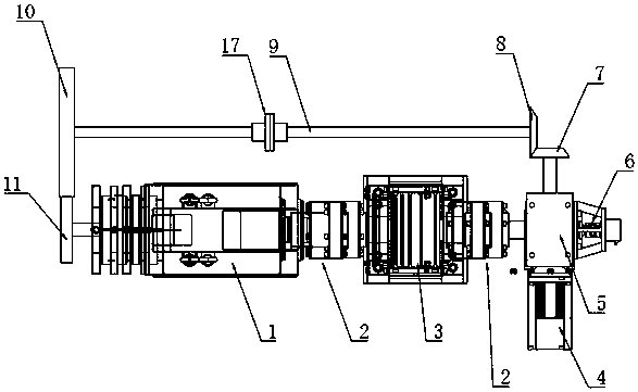
[0039] Embodiment 3: An elevator double machine traction device (see image 3 ) is different from Embodiment 1 in that the transmission rod 9 is provided with a clutch. The clutch in this embodiment adopts an electromagnetic clutch 17. When the power is applied, the clutch maintains the transmission, and the synchronous mechanism drives the worm to rotate synchronously without causing lock to the worm gear. stop; when there is no electricity, the clutch disconnects the transmission. At this time, the synchronous mechanism has no power input, and will not drive the worm to rotate, and the worm will lock the worm wheel, and finally lock the traction sheave. Refer to Example 1 for all the other structures.


PUM


Abstract

The invention relates to a double-machine traction device, and solves the defects of incapability of quickly braking a car, low braking reliability and low elevator safety easily caused by insufficient braking force due to emergent braking in a traditional elevator through a brake. The double-machine traction device comprises a tractor, a traction wheel, a worm gear mechanism, a rescue motor and asynchronous mechanism. A worm wheel is coaxially connected with the traction wheel, and is synchronously rotated with the traction wheel; through a mechanical transmission mode, the synchronous mechanism is connected with a worm rod, and drives the worm rod to maintain synchronous rotation with the worm wheel; and the worm rod is driven to rotate only during rescuing. The worm rod is engaged withthe worm wheel to form a locking mechanism of the traction wheel, so that the reliable braking of the traction wheel can be realized when an elevator system is powered off or failed, and the accidents of roof collision or bottom collision of cars are effectively prevented; and the rescue motor drives the worm rod to drive the traction wheel to rotate to realize timely rescue.

Description

technical field [0001] The invention relates to a traction device, in particular to a double-machine traction device with a main traction motor and a rescue motor. Background technique [0002] In high-rise buildings, in order to adapt to the needs of height changes, lifting devices are a necessary supporting equipment, such as elevators, which can bring great convenience to users. [0003] An elevator is a vertical elevator powered by a motor, also known as a vertical elevator. The vertical elevator is equipped with a box-shaped gondola, which is used for multi-storey buildings to take people or carry goods. From the earliest first-step safety elevator to the modern automatic control elevator, although it has been developed for hundreds of years, most of the elevators are driven by a traction drive mechanism, including a traction machine set on the top of the hoistway. The traction machine is connected to the traction wheel, and there is a traction rope on the traction wh...

Claims


Application Information

Patent Timeline
Patent Type & Authority Applications(China)
IPC IPC(8): B66B5/16B66B5/02
CPCB66B1/365B66B5/00B66B5/0018B66B5/0031B66B5/0037B66B5/005B66B5/0087B66B5/0093B66B5/021B66B5/027B66B5/028B66B5/04B66B5/044B66B5/08B66B5/16B66B5/22B66B5/26B66B7/02B66B7/06B66B7/08B66B9/00B66B11/0005B66B11/0035B66B11/0226B66B11/0293B66B11/04B66B11/0415B66B11/043B66B11/0446B66B11/08B66B13/12B66B13/125B66B13/165B66B17/12
Inventor 陈庆邓健李军
Owner SHAANXI SIUSAI ELECTROMECHANICAL TECH CO LTD
Why Eureka
Try Eureka