Cantilever type rotor used for backing turbine air blowing loss test

A blast loss, cantilever technology, applied in the direction of blade support elements, engine elements, machines/engines, etc., can solve the problems of long cycle, complex structure and lubrication of both ends of the support system, high cost, and achieve the effect of simple structure

Pending Publication Date: 2019-04-23
中国船舶重工集团公司第七0三研究所
View PDF0 Cites 0 Cited by
  • Summary
  • Abstract
  • Description
  • Claims
  • Application Information

AI Technical Summary

Problems solved by technology

[0004] In order to solve the problems of high cost, long period, and relatively complex structure and lubrication of t

Method used


Image

  • Cantilever type rotor used for backing turbine air blowing loss test
  • Cantilever type rotor used for backing turbine air blowing loss test
  • Cantilever type rotor used for backing turbine air blowing loss test

Examples


specific Embodiment approach 1

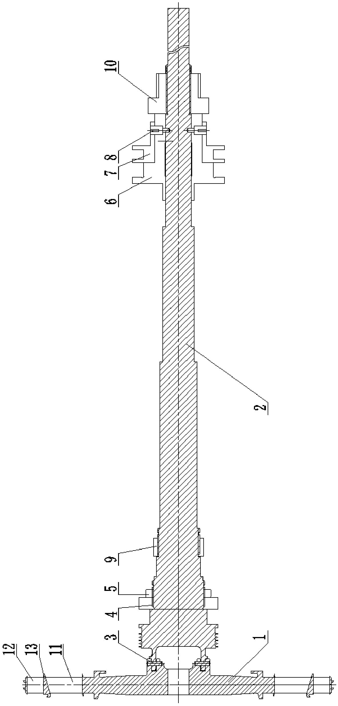
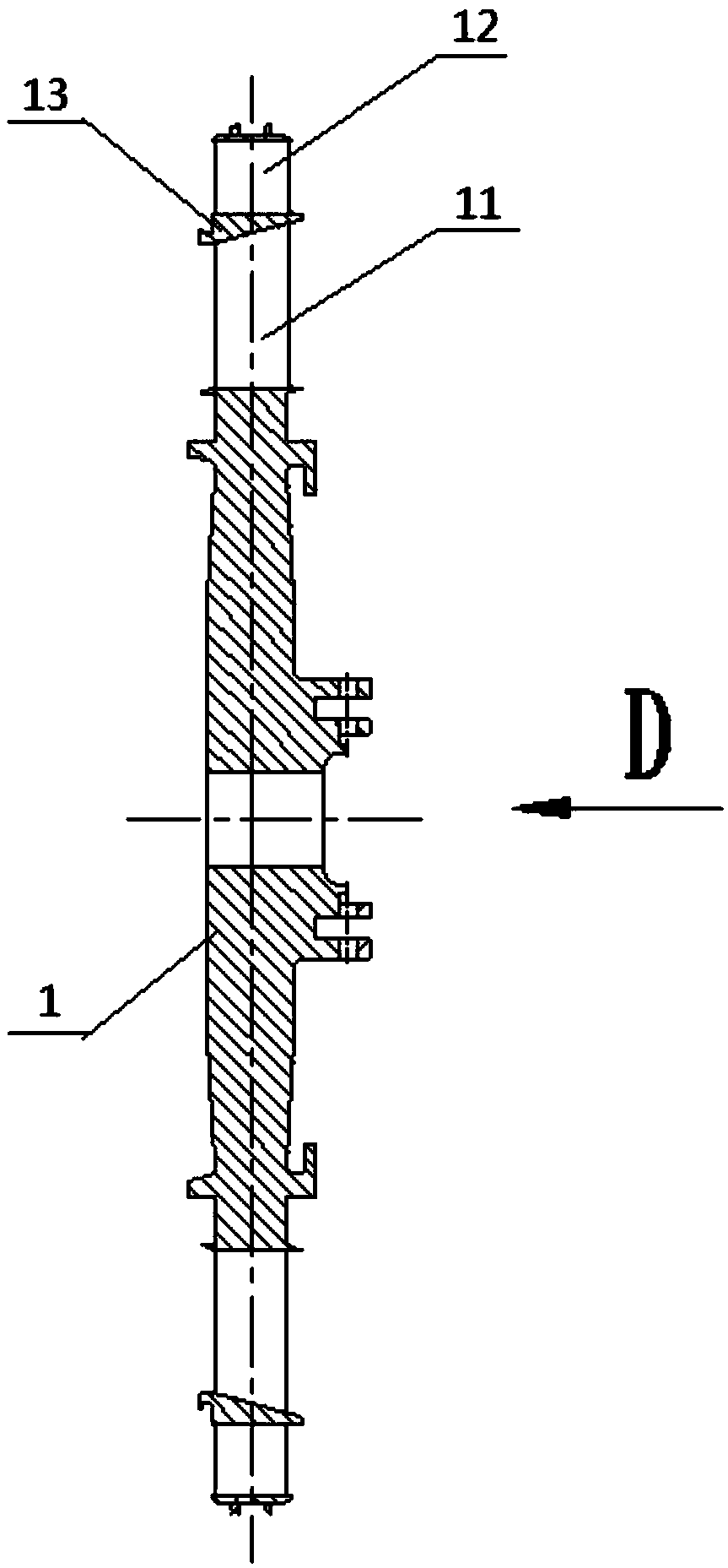
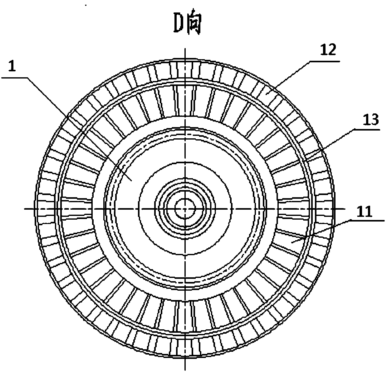
[0017] Specific implementation mode one: combine Figure 1 to Figure 4 Describe this embodiment, a cantilevered rotor used for the blowing loss test of a reversible turbine, which includes a turbine integral blade disk, and it also includes a reversible turbine output shaft 2, a disk shaft connecting pin 3, a forward turning blade 11, The intermediate ring 13 and the reverse turbine blade 12, the forward moving blade 11 is installed on the overall turbine blade disc, the reverse turbine blade 12 is installed on the forward moving blade 11 through the intermediate ring 13, the overall turbine blade disc, the forward moving blade 11, The intermediate ring 13 and the reversing turbine blades 12 together form a reversible turbine double-layer integral blade disc 1, and one end of the reversible turbine output shaft 2 is connected to the reversible turbine double-layer integral blade disc 1 through a disk shaft connecting pin 3, and the reversible turbine output One end of the shaf...

specific Embodiment approach 2

[0019] Specific implementation mode two: combination figure 1 and Figure 9 The present embodiment will be described. In this embodiment, the blade profiles of the forward moving blade 11 and the reverse turbine blade 12 are in opposite directions. Such setting can satisfy the power output in different rotation directions, thus having the functions of forward driving and reverse driving. Other compositions and connections are the same as in the first embodiment.

[0020] The included angle A between the blade surfaces of the forward moving blade 11 and the reverse turbine blade 12 in this embodiment is 126 degrees.

specific Embodiment approach 3

[0021] Specific implementation mode three: combination figure 1 and Figure 4 To illustrate this embodiment, the reversible turbine output shaft 2 in this embodiment is a stepped shaft, and the diameter of the reversible turbine output shaft 2 decreases sequentially from left to right. Such setting facilitates the installation and axial positioning of the bearing. Other compositions and connections are the same as those in Embodiment 1 or Embodiment 2.


PUM


Abstract

The invention discloses a cantilever type rotor used for a backing turbine air blowing loss test and relates to a cantilever type rotor. The cantilever type rotor used for the backing turbine air blowing loss test solves the problems that in a traditional wheel disk and blade rotor test, cost is high, the period is long, and lubricating of bearing system structures at the two ends is relatively complicated. A forward vehicle moving blade (11) is installed on a turbine overall blade disk; a backing turbine blade (12) is installed on the forward vehicle moving blade (11) through a middle ring (13); the turbine overall blade disk, the forward vehicle moving blade (11), the middle ring (13) and the backing turbine blade (12) jointly form a backing turbine double-layer overall blade disk (1); one end of a backing turbine output shaft (2) is connected with the backing turbine double-layer overall blade disk (1) through a disk shaft connection pin (3), and one end of the backing turbine output shaft (2) is suspended; and the backing turbine double-layer overall blade disk (1) is located on the outer sides of two supporting bearing supporting points of a whole rotor. The cantilever type rotor is used for the backing turbine air blowing loss test

Description

technical field [0001] The invention relates to a cantilever rotor, in particular to a cantilever rotor used for a reversible turbine blowing loss test. Background technique [0002] Since its birth, gas turbines have been favored by various countries due to their high power density and quick response. As one of the main power devices of the ship, the gas turbine cannot be reversed directly, which is a major defect. At present, the reversing problem of gas turbines in my country is realized through variable pitch propellers. While variable pitch propellers use conventional gearboxes and provide balanced thrust control, they have certain limitations and some disadvantages. First of all, it has a certain upper limit to the transmission power, and it will pay a higher price after exceeding this power. Secondly, the size and weight of variable-pitch propellers, shafting and bearings matched with high-power gas turbines are much larger and more expensive than conventional fixe...

Claims


Application Information

Patent Timeline
IPC IPC(8): F01D5/02F01D25/16
CPCF01D5/022F01D25/16
Inventor 牛夕莹郁顺旺李国强霍玉鑫
Owner 中国船舶重工集团公司第七0三研究所
Why Eureka
Try Eureka