Two-stage liquid ring vacuum pump and assembling method thereof

A liquid ring vacuum pump and secondary pump technology, which is applied to the components, pumps, and pump components of the pumping device for elastic fluids, and can solve the problems of difficulty in ensuring the consistency of the four gaps, long assembly hours, and damage. , to achieve the effect of improving performance, safety and stability, simplifying assembly process, and improving assembly efficiency

Active Publication Date: 2019-04-23
淄博真空设备厂有限公司
View PDF10 Cites 0 Cited by
  • Summary
  • Abstract
  • Description
  • Claims
  • Application Information

AI Technical Summary

Problems solved by technology

At present, it is theoretically possible to achieve the same size of each gap, but in the actual assembly process, the assembly gap often changes due to factors such as cumulative tolerances and assembly deformation, so two or more adjustments are required, and the assembly time is long. The efficiency is low, and in the process of use, it will also be affected by uncontrollable factors such as deformation and wear during use. It is difficult to ensure the consistency of the four gaps. In this way, there will still be gaps of different sizes in the later use process, and the gaps are large. In order to easily cause the air volume and vacuum degree to drop, the gap is small, it is easy to cause impeller damage such as wear and stuck, and the maintenance frequency is high, and usually, the gap between any impeller and one side becomes larger (or smaller), and the gap between any impeller and the other side The gap will be correspondingly smaller (or larger), and the adverse effects will be two-sided

Method used


Image

  • Two-stage liquid ring vacuum pump and assembling method thereof
  • Two-stage liquid ring vacuum pump and assembling method thereof
  • Two-stage liquid ring vacuum pump and assembling method thereof

Examples


Embodiment Construction

[0042] Embodiments of the present invention are further described below in conjunction with accompanying drawings:

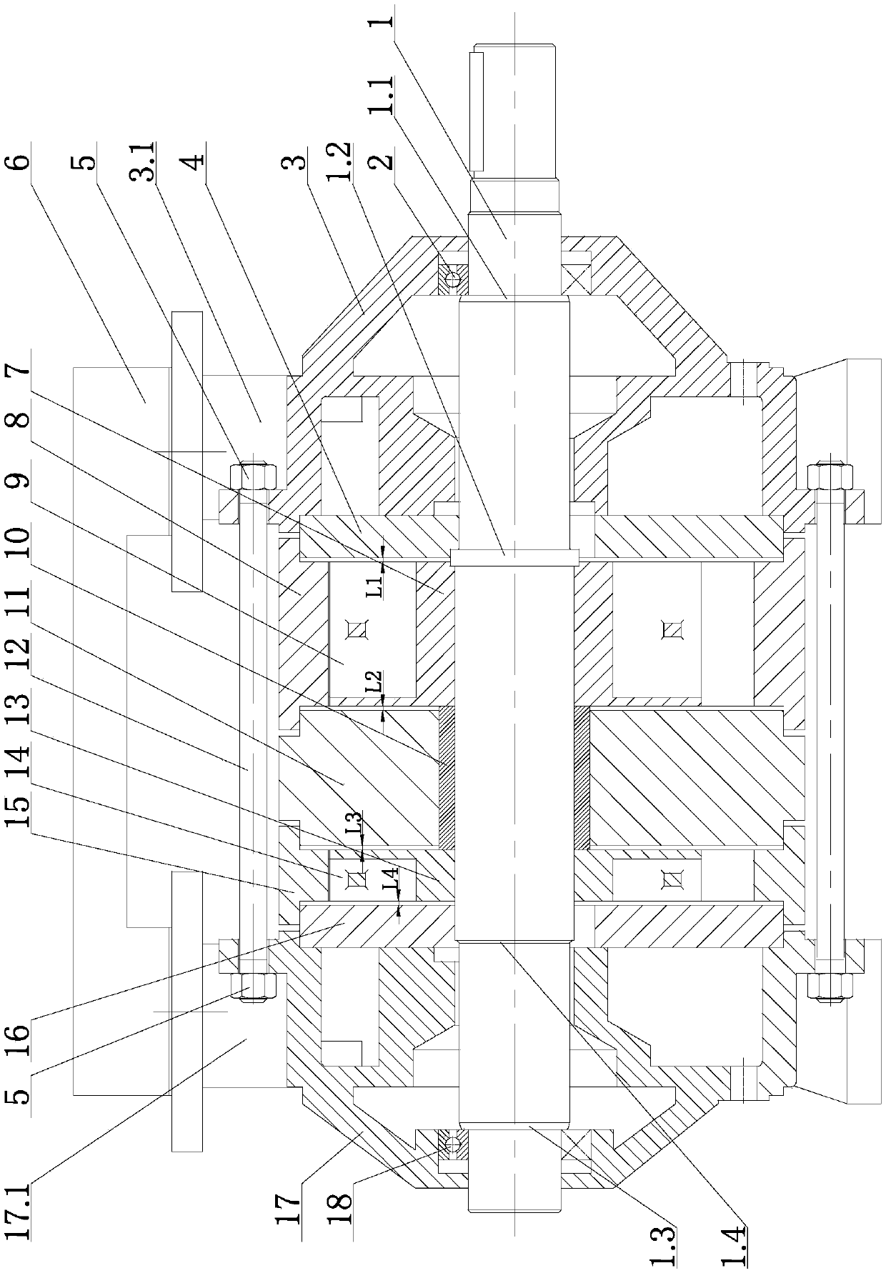
[0043] Such as Figure 1~6 As shown, the two-stage liquid ring vacuum pump of the present invention includes a primary pump body and a secondary pump body assembled on the same main shaft 1 . in:

[0044] The first-stage pump body is composed of the first-stage pump casing 8, the front pump cover 3, and the middle wall 11, and the second-stage pump body is composed of the second-stage pump casing 15, the rear pump cover 17, and the middle wall 11, that is, the two-stage pump bodies share a middle wall. The wall 11, the intermediate wall 11 and the first-stage pump casing 8 and the second-stage pump casing 15 on both sides thereof are fixedly assembled by using seams, and the limiting bushing 10 is installed on the main shaft 1, and the intermediate wall 11 and the limiting bushing 10 are in clearance fit. . Because there is no gas channel on the intermediate ...


PUM


Abstract

The invention belongs to the field of liquid ring pumps, and particularly relates to a two-stage liquid ring vacuum pump and an assembling method thereof. The two-stage liquid ring vacuum pump is reasonable in structural design, the two-stage liquid ring vacuum pump is provided with two stage compressing chambers, a gas passage is not arranged on a middle wall, the two stage compressing chambers can be communicated directly through an external communication tube, and therefore, in the assembly process, only the numerical values of the gaps L1 and L4 need to be controlled, the gap L2 and the gap L3 are naturally formed by the machining size and do not need to be controlled, so that the assembly clearance is easily ensured, and on the premise that the air extraction amount and the vacuum degree are not affected, the assembly process can be simplified, the assembling efficiency is improved, and the using performance and the safety stability are improved, meanwhile, compared with a traditional two-stage pump, the production noise can be greatly reduced, and the noise pollution can be reduced. According to the method for assembling the two stage liquid ring vacuum pump, the gap L1 and gap L4 can be completely controlled, the assembly precision of the whole pump body is ensured, the assembly process is further simplified, and the assembly efficiency is improved.

Description

technical field [0001] The invention relates to a two-stage liquid ring vacuum pump and an assembly method thereof, belonging to the field of liquid ring pumps. Background technique [0002] With the continuous development of basic industries, vacuum equipment requires higher stability, especially higher performance, efficiency and operational reliability in the high vacuum stage. [0003] Traditional liquid ring pumps are limited by the temperature of the working fluid in actual work, especially when they lose their pumping capacity in the high vacuum stage. At the same time, because of the high compression ratio, it is easy to cause cavitation in the air cavity and damage components. [0004] Therefore, in order to solve this problem, technicians have developed a two-stage compression vacuum pump (referred to as a two-stage pump), which has two-stage compression chambers, and impellers and suction and exhaust discs (structures such as Figure 7 shown), and the two-stage co...

Claims


Application Information

Patent Timeline
IPC IPC(8): F04C19/00F04C23/00F04C29/06F04C29/00
CPCF04C19/00F04C23/001F04C29/00F04C29/06F04C2240/80
Inventor 贺红霞徐法俭巩泽龙黄志婷
Owner 淄博真空设备厂有限公司
Why Eureka
Try Eureka