New energy tensioner and working method thereof

A new energy and tension machine technology, applied in the direction of mechanical equipment, emergency power arrangement, fluid pressure actuation device, etc., can solve the problems of energy waste, no energy conversion and utilization, etc., to reduce costs, improve power generation effect, and save energy Effect

Pending Publication Date: 2019-04-23
蒋晓峰
View PDF0 Cites 7 Cited by
  • Summary
  • Abstract
  • Description
  • Claims
  • Application Information

AI Technical Summary

Problems solved by technology

[0004] Because the main working state of the tension machine is the tension working condition, that is, the passive working condition, and in the tension machine of the original conventional design, under the passive working condition of the tension, the tension is adjusted by adjusting the tension adjustment valve to adjust the pressure of the main hydraulic circuit, which is different from the tension wheel The resistance of stable operation corresponds to the size, while the tension adjustment valve only converts the hydraulic energy into the heat of the hydraulic oil, and dissipates heat through the radiator, which does not fully convert and utilize this part of the energy, and under this working condition, the engine still needs to It does work to provide pressure oil for stable operation of fan motors, tail car motors, etc. Therefore, there is an obvious waste of energy

Method used


Image

  • New energy tensioner and working method thereof
  • New energy tensioner and working method thereof
  • New energy tensioner and working method thereof

Examples


example 1

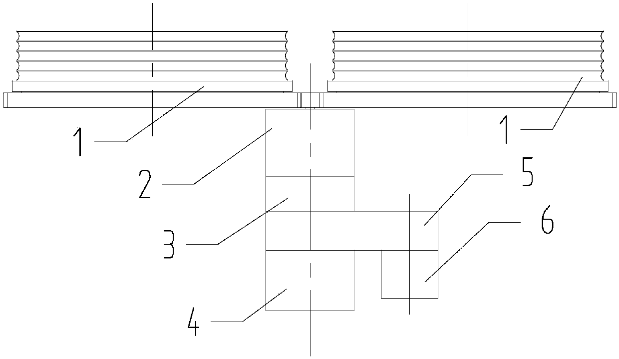
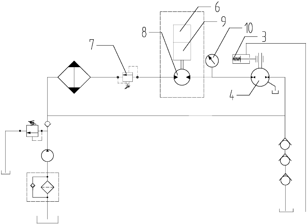
[0033] Such as figure 1 , 3 As shown in 4, a new energy tension machine includes a mechanical structure part, a hydraulic system part, a control system part and a power device part. The mechanical structure part includes a tension wheel 1, a first gear box 2 connected to the tension wheel 1, and The brake 3 connected to the first gear box 2, the transfer case 5 connected to the brake 3, and the generator 6 connected to the transfer case 5; the hydraulic system part includes a hydraulic circuit, a tension regulating valve 7 arranged on the hydraulic circuit, and tension Table 10, main hydraulic motor 4, main hydraulic pump 13, main hydraulic pump charge pump 14, fan pump 16, tail car pump 17, brake charge pump 18, brake 3 connected to main hydraulic motor 4, fan pump 16 and tail car pump 17 is connected, the tail car pump 17 is connected to the brake charge pump 18, the main hydraulic pump 13 is connected to the main hydraulic pump charge pump 14, and it also includes the part co...

example 2

[0046] The difference from the first example above is that the generator 6 is arranged in the mechanical structure part, and a speed increasing mechanism is arranged at the large gear of the tension wheel 1, and the generator 6 is connected to the speed increasing mechanism. The generator 6 is connected through the speed increasing mechanism, which can realize the acceleration on the generator 6 side and improve the power generation effect.

example 3

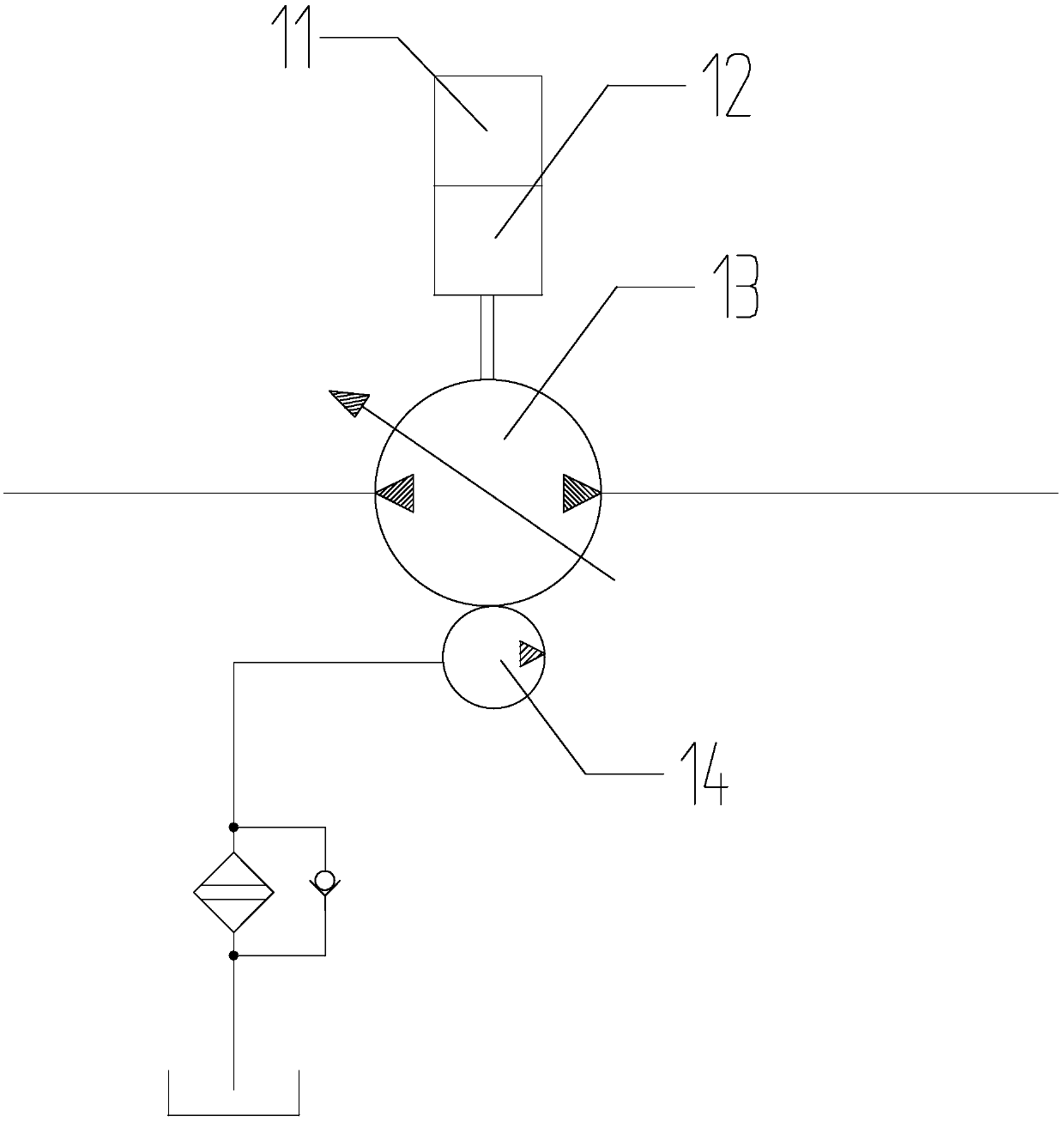
[0048] Such as figure 2 As shown, the difference from the above example 1 is that the generator 6 is installed in the hydraulic system, and the hydraulic circuit between the tension adjustment valve 7 and the tension meter 10 is equipped with a hydraulic drive motor 8 that drives the generator 6 to generate electricity. The machine 6 is connected to a hydraulic drive motor 8 through a second gear box 9. The generator 6 is connected to the hydraulic drive motor 8 through the second gear box 9 to achieve drive power generation under passive working conditions. The second gear box 9 can effectively increase the speed and improve the power generation effect.

[0049] the above Figure 1-4 The shown new energy tension machine and its working method are specific embodiments of the present invention, which have already embodied the essential features and progress of the present invention, and can be shaped according to actual needs and under the enlightenment of the present invention. ...


PUM


Abstract

The invention discloses a new energy tensioner and a working method thereof and relates to the field of tensioners. At present, a tensioner used in construction of line stringing under tension in transmission line engineering basically adopts a diesel engine as a power, the equipment noise is large, the environment is polluted, the engine is relatively high in maintenance cost and relatively poorin economy, and the field diesel filling easily causes pollution at the same time. For the new energy tensioner, by fully utilizing the characteristic that a tensioner mainly focuses on passive worksand adding a power generator, a power battery, a motor for driving a hydraulic pump and the like, the original diesel engine is cancelled, so that external passive work is converted to an electric energy as much as possible, and the electric energy is provided to the motor for driving the hydraulic pump; meanwhile, the configured power battery can store redundant electric energy and can provide the power to a system if needed by the system, so that work of the tensioner saves more energy; and after the diesel engine is cancelled, pollution to the surrounding environment can not be caused, andequipment running noise can be greatly reduced, the operation environment is optimized, and higher environmental protection requirements are realized.

Description

Technical field [0001] The invention relates to the field of tension machines, in particular to a new energy tension machine and its working method. Background technique [0002] Tension machines are used in the construction of the transmission line project. The current tension machines use diesel engines to provide power. Not only the equipment is noisy, pollutes the environment, the engine is relatively high in maintenance costs and economical, and at the same time, diesel fuel is added on site. It is also easy to cause pollution. [0003] The original conventional tension machine is mainly composed of tension wheel, deceleration mechanism, hydraulic system, engine, etc., and its working state is generally: when the tension machine is in place, the engine drives the corresponding hydraulic pump to provide the outrigger cylinder with the pressure oil for the cylinder expansion; Under tension conditions, the engine drives the corresponding hydraulic pump to provide the pressure oi...

Claims


Application Information

Patent Timeline
Patent Type & Authority Applications(China)
IPC IPC(8): F15B21/08F15B21/14B65H59/00H02J7/32H02J9/04
CPCF15B21/087B65H59/00B65H2701/34F15B21/14H02J7/32H02J9/04
Inventor 蒋晓峰
Owner 蒋晓峰
Why Eureka
Try Eureka