Testing system for shield tunnel excavation face stability-losing centrifugal model test under seepage condition

A technology of centrifugal model test and shield tunnel, which is applied in the direction of applying stable tension/pressure to test material strength, measuring force, measuring device, etc. It can solve the problems of large size of electrical sensors, mutual interference of signal transmission, and current collection Problems such as ring space, to achieve good economic and social benefits, convenient deformation, and reasonable scheme

Inactive Publication Date: 2019-04-23
CHANGAN UNIV
View PDF7 Cites 13 Cited by
  • Summary
  • Abstract
  • Description
  • Claims
  • Application Information

AI Technical Summary

Problems solved by technology

It can be seen that it is necessary to study the relationship between the ultimate support force of the shield tunnel excavation face and the longitudinal slope angle of the tunnel, but the device does not introduce the relevant content; finally, the instrument used to test the support force of the excavation face is a pressure sensor , is greatly affected by the electromagnetic environment of the test field, and a large bundle of wires formed by the lead-out lines of each measuring point is bundled into bundles, occupying most of the collector ring space, and mutual interference during signal transmission greatly affects the test accuracy
In addition, the size of the geotechnical centrifugal model is small, and the length is between 0.20 and 1.5m. The size of the traditional electrical sensor is generally too large, which will have a great impact on the model under the action of gravity. Therefore, the centrifugal model test requires high speed and stability. , Signal conversion, transmission and processing system with strong anti-interference ability

Method used


Image

  • Testing system for shield tunnel excavation face stability-losing centrifugal model test under seepage condition
  • Testing system for shield tunnel excavation face stability-losing centrifugal model test under seepage condition
  • Testing system for shield tunnel excavation face stability-losing centrifugal model test under seepage condition

Examples


Embodiment Construction

[0023] The present invention will be further described below in conjunction with the drawings.

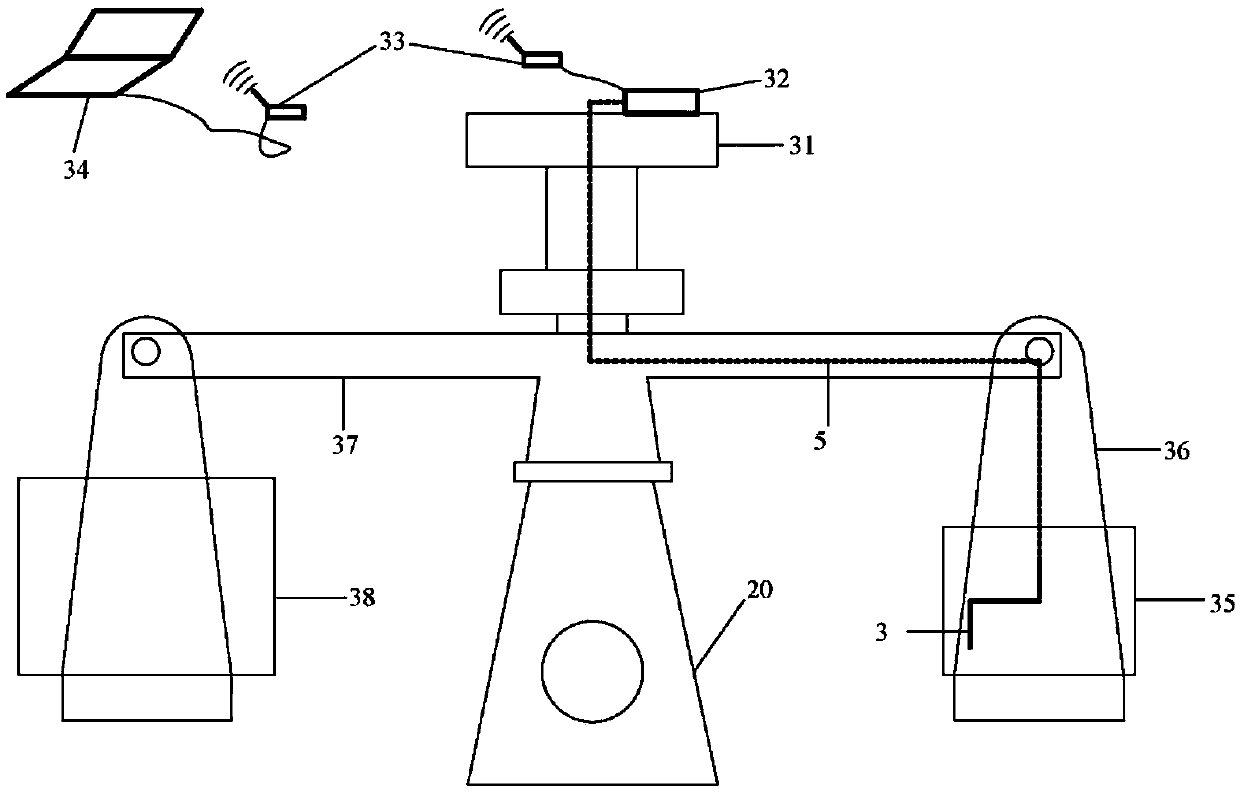
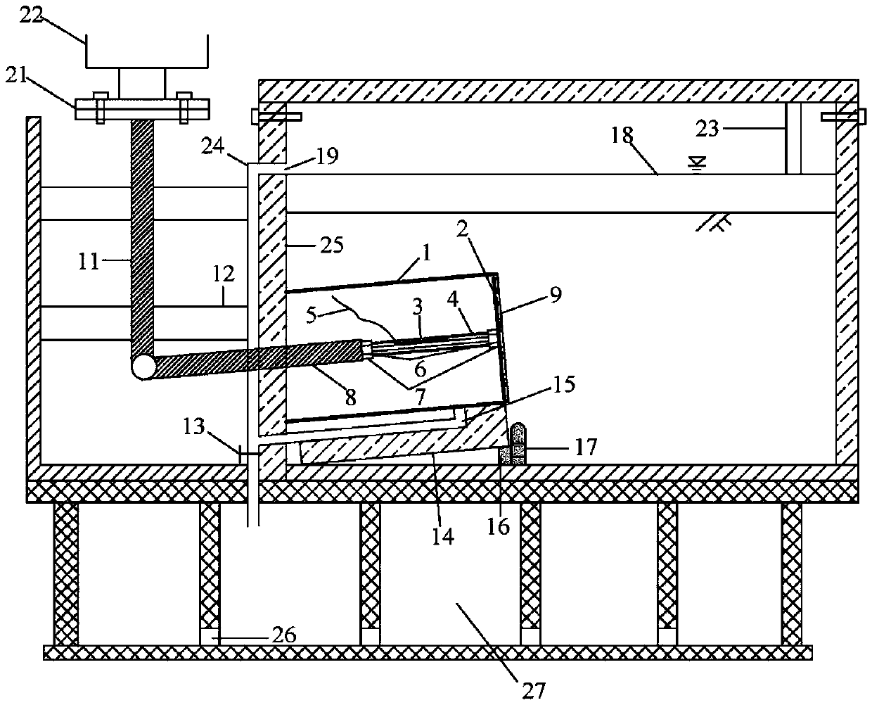
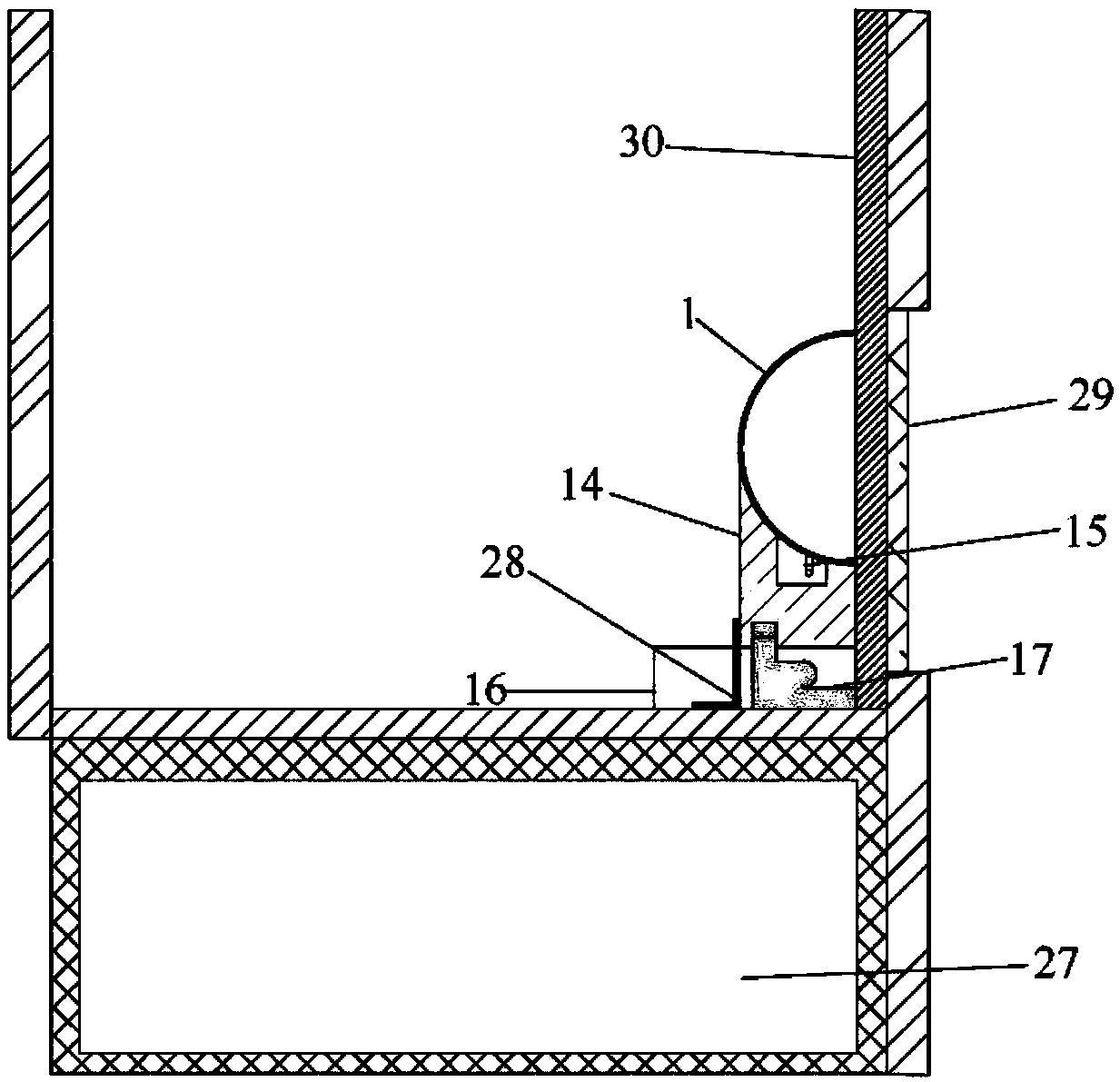
[0024] See figure 1 , figure 2 with image 3 , The present invention includes a model box 35 for fixing in the upper basket 36 of the geotechnical centrifuge 20;

[0025] The model box 35 includes a test box. The test box is provided with a cavity composed of a semicircular shield shell 1 and an excavation panel 2. The bottom of the cavity is provided with an angle adjustment device, and the outer surface of the excavation panel 2 is covered with a PVD permeable membrane. 9. One side of the test box is provided with a vertical partition 25, and a number of overflow holes 19 are provided on the vertical partition 25. The water level 18 and the overflow hole 19 have the same height. A water supply pipe 23 is provided on the top of the test box. There is a civil centrifuge manipulator 22 outside. The civil centrifuge manipulator 22 is connected to the second transfer rod 11, the second tr...


PUM


Abstract

The invention discloses a testing system for a shield tunnel excavation face stability-losing centrifugal model test under the seepage condition. An FBG sensor of the testing system guides out a signal through an optical fiber grating, an advanced optical fiber grating sensing technology is used for the shield tunnel excavation face stability-losing centrifugal model test under the seepage condition firstly, the change characteristics of supporting force of the excavation face in the shield tunnel excavation face stability-losing process can be obtained in high-precision and real-time modes, and actual shield tunnel construction is guided. The displacement and retreat rates of an excavation face plate are controlled precisely in real time in a centrifugal field through a geotechnical centrifuge manipulator, the shield tunnel excavation face stability-losing centrifugal model test at different tunnel longitudinal slope angles is achieved through the geotechnical centrifuge manipulator and an angle adjusting device, the conception is ingenious, implementing is easy, and the testing system is reasonable in scheme, simple in structure and conventional in use equipment, and has good economic benefits and social benefits.

Description

Technical field [0001] The invention belongs to the field of tunnel model tests, and specifically relates to a centrifugal model test system for instability of a shield tunnel excavation surface under seepage conditions. Background technique [0002] The stability control of the excavation surface in shield tunnel construction is still a problem to be solved urgently, and the reasonable selection of the support force of the excavation surface is the core issue to solve this problem. The supporting force of the excavation surface is an important reason that affects the stability of the excavation surface and causes soil disturbance. If it is not properly controlled, serious safety accidents will occur. Too little supporting force causes a large amount of soil in front of the excavation to enter the pressure chamber, causing the surface to collapse, while excessive supporting force is likely to cause surface uplift problems and adversely affect surrounding buildings. Therefore, the...

Claims


Application Information

Patent Timeline
Patent Type & Authority Applications(China)
IPC IPC(8): G01N3/08G01L1/24
CPCG01L1/246G01N3/08
Inventor 翁效林孙钰丰严彬华张鹏田超李豪王利明张丙武王伟龙牛豪爽
Owner CHANGAN UNIV
Why Eureka
Try Eureka