Multi-input parallel and multi-output parallel power converter

A power converter, multi-channel output technology, applied in output power conversion devices, DC power input to DC power output, instruments, etc. Reliability, increased power levels, increased output current and power effects

Pending Publication Date: 2019-04-23
SHENZHEN UUGREENPOWER ELECTRIC CO LTD
View PDF0 Cites 3 Cited by
  • Summary
  • Abstract
  • Description
  • Claims
  • Application Information

AI Technical Summary

Problems solved by technology

It solves the problem of serious unbalanced power of multi-channel power converters on the primary side caused by the difference in device parameters, and solves the problem of current sharing when multiple output rectifier circuits are connected in parallel

Method used


Image

  • Multi-input parallel and multi-output parallel power converter
  • Multi-input parallel and multi-output parallel power converter
  • Multi-input parallel and multi-output parallel power converter

Examples


Embodiment 1

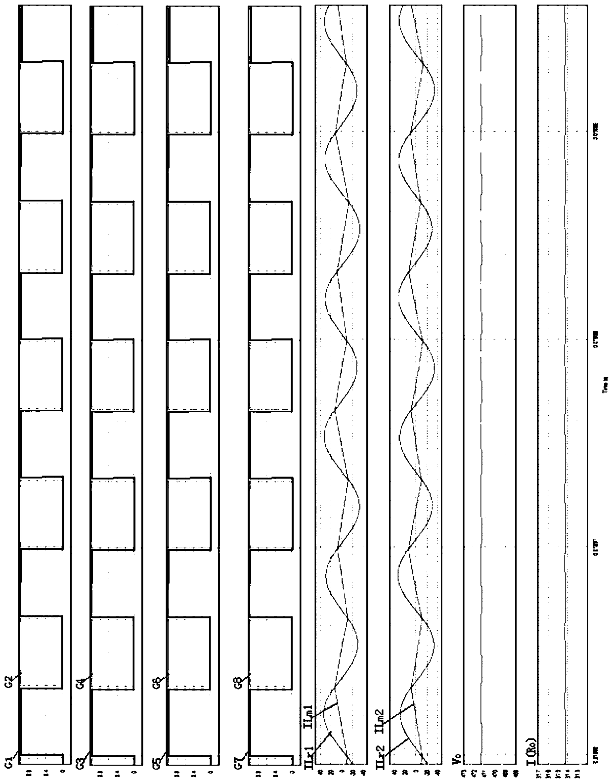
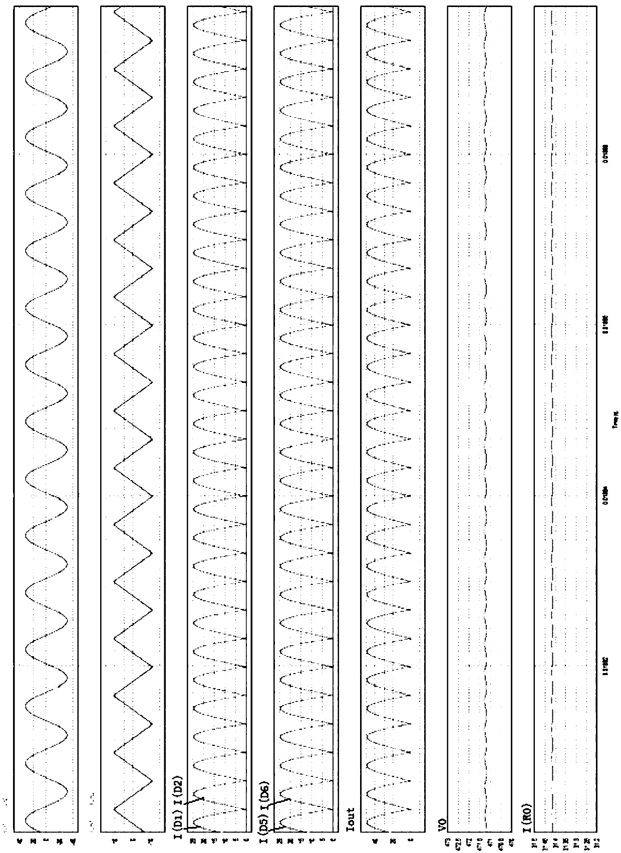
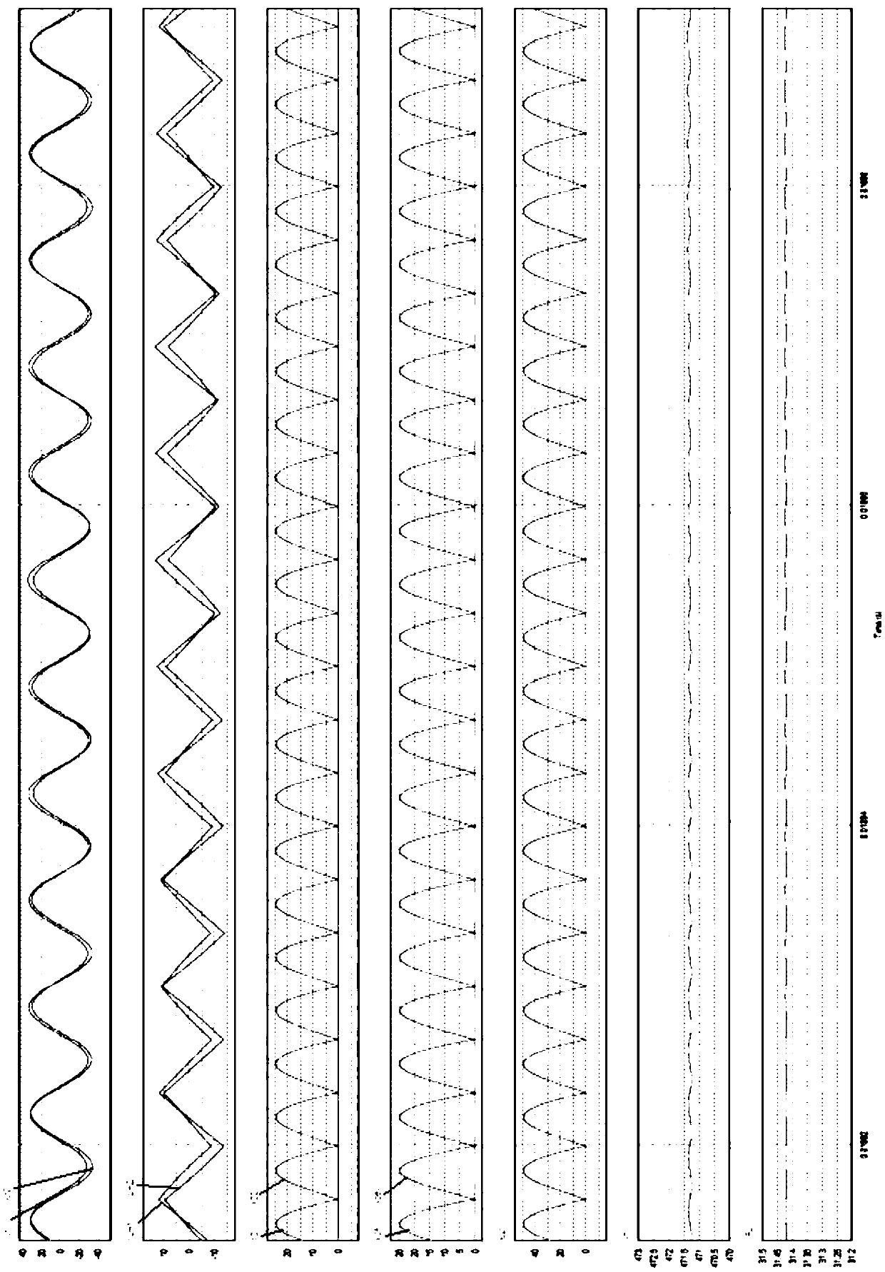
[0058] figure 1 It is a schematic diagram of circuit function connection of a power converter with multiple inputs connected in parallel and multiple outputs connected in parallel according to Embodiment 1 of the present invention. The power converter includes a power supply circuit, a switch network 1 , an inductor-capacitor combination module 2 , a transformer module 3 , a rectifier module 4 and a filter module 5 which are connected in sequence. The power circuit is a voltage source circuit Uin. The voltage source circuit Uin in Embodiment 1 can be a single-phase passive power factor correction circuit, or a single-phase active power factor correction circuit, or a three-phase passive power factor correction circuit, or a three-phase active power factor correction circuit in practical applications. Voltage source circuits such as factor correction circuits.

[0059] see figure 1 , the power converter in Embodiment 1 is a power converter with two inputs connected in parall...

Embodiment 2

[0081] Embodiment 2 is a power converter structure with two inputs in parallel and three outputs in parallel power converter extended on the basis of the power converter in embodiment 1 with two inputs in parallel and two outputs in parallel. The difference is that the first transformer module 101 further includes a fifth transformer T5, the second transformer module 102 further includes a sixth transformer T6, and the rectification circuit further includes a third rectification circuit.

[0082] Figure 15 It is a schematic diagram of circuit function connection of a two-way input parallel connection and three-way output parallel connection power converter according to Embodiment 2 of the present invention. The primary side of the first transformer T1, the second transformer T2 and the fifth transformer T5 are connected in series as the input terminal to the output terminal of the first inductance-capacitance combination module 201; the primary sides of the third transformer ...

Embodiment 3

[0086] Embodiment 3 is a multi-input parallel multi-output parallel power converter topology based on the power converter with two inputs connected in parallel and three outputs connected in parallel in Embodiment 1. The difference is that the first transformer module 201 and the second transformer module 202 include more than three transformers, the number of transformers included in the first transformer module 201 and the second transformer module 202 is equal, and the specific circuit connection method is similar to that of Embodiment 2 .


PUM


Abstract

The invention discloses a multi-input parallel and multi-output parallel power converter. The power converter comprises a switch network, an inductor-capacitor combination module, a transformer module, a rectifier module and a filter module, the switch network, the inductor-capacitor combination module, the transformer module, the rectifier module and the filter module are connected in order; theswitch network comprises multiple parallel identical switching circuits; the transformer module comprises a plurality of transformer sets, the transformer sets comprises a plurality of same transformers in which the primary windings are connected in series, and the transformer sets are in one-to-one correspondence connection with the switch circuit; the rectifier module comprises a plurality of rectifying circuits, and the output of the rectifying circuits are connected in parallel; the secondary windings are connected in series of the corresponding transformers in the transformer sets, and the secondary windings are connected in series and then are connected with the corresponding rectifying circuits in the rectifier module for rectification.

Description

technical field [0001] The invention relates to the field of power converters, in particular to a structure of a power converter in which multiple inputs are connected in parallel and multiple outputs are connected in parallel. Background technique [0002] At present, high-power and high-frequency DC / DC power converters have always been a research hotspot in the power electronics industry. However, due to the limitation of the production process of a single power device switch tube, the internal resistance of the power device cannot be infinitely small, and the reverse recovery characteristics need to be constantly improved. promote. Based on the current power devices, in order to develop high-power high-frequency DC / DC converters, in many cases, multiple switching tubes must be connected in parallel, but multiple switching tubes in parallel work under high-frequency conditions, and the driving and current sharing Problems will greatly affect product reliability in actual ...

Claims


Application Information

Patent Timeline
Patent Type & Authority Applications(China)
IPC IPC(8): H02M3/335
CPCH02M3/33592
Inventor 柏建国邓礼宽
Owner SHENZHEN UUGREENPOWER ELECTRIC CO LTD
Why Eureka
Try Eureka