Supercharge Your Innovation With Domain-Expert AI Agents!

A loom electronic take-up control method

A control method and technology of electronic rolling, applied in looms, textiles, textiles and papermaking, etc., can solve problems such as driving marks, achieve the effects of reducing tolerance manufacturing requirements, eliminating gear gaps, and saving manufacturing costs

Active Publication Date: 2020-12-29
SHANDONG RIFA TEXTILE MACHINERY
View PDF6 Cites 0 Cited by
  • Summary
  • Abstract
  • Description
  • Claims
  • Application Information

AI Technical Summary

Problems solved by technology

If the loom runs normally or the loom only rotates in one direction, the gear meshing is all attached to one side of the direction of rotation, and the gap has no effect at this time; but when the loom changes direction, the servo motor will rotate after a certain angle. Only then can the gear mesh and stick to the other side to eliminate the gap. At this time, the take-up roller starts to rotate. For fabrics with small weft density, driving marks often appear in this case.

Method used


Image

  • A loom electronic take-up control method
  • A loom electronic take-up control method

Examples


Embodiment 1

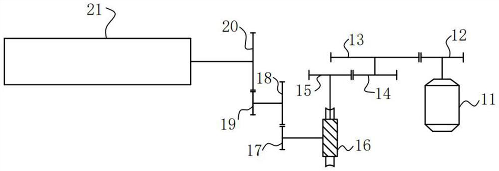
[0018]Such asfigure 1 As shown, there is inevitably a gap in the meshing of each gear. Through the amplification of the multi-stage transmission, the gap to the winding roller will be very large.

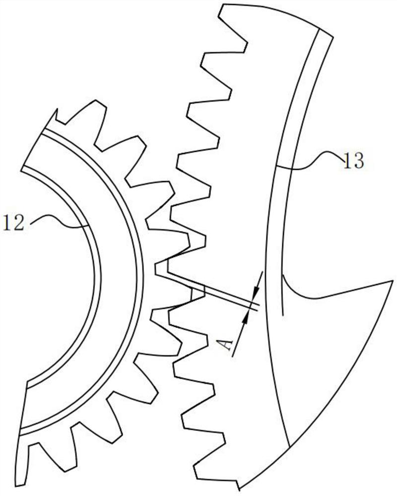
[0019]Such asfigure 2As shown, in this control method, when the rotation direction of the loom changes, the servo motor first adopts a torque control method to control the torque so that the first gear 12 connected to the servo motor is close to the second gear 13 in the opposite direction of the previous movement direction to eliminate the gear gap After A, the servo motor switches to position control mode. The operation of the loom can only be divided into express (only forward rotation), slow (inching forward and reverse rotation), and slow weft insertion (only forward rotation). When the loom stops, it will brake first and then automatically reverse to the positioning angle to stop. under. The rotation direction changes of the loom include: reversal of fast parking positioning, forward-r...

Embodiment 2

[0022]On the basis of traditional pulse + direction (also can be forward and reverse pulse, AB phase pulse and other well-known position control methods), alarm, alarm reset, S-ON, 24V, 0V, the main control computer adds position-torque switching signal and Torque limit signal. The position-torque switching signal is torque control when OFF, and position control when ON; the torque limit signal is to set a maximum torque limit value in the range of -100%-+100% torque, which can be used by the host computer -10V--+10V voltage signal control is realized, and the set value is determined according to the actual weaving situation.

[0023]When the loom is running and stopped, the main shaft is braked by the brake disc, and then slowly reverses to the positioning stop angle to stop. At this time, the take-up servo motor is position controlled and the spindle rotates to the brake stop position, and then the main control computer gives a switching signal OFF, the servo drive switches to torque...


PUM


Abstract

The invention discloses an electronic take-up control method for a loom. When the rotating direction of the loon is changed, a servo motor adopts a torque control manner, a first gear connected with the servo motor draws close to a second gear along a direction opposite to a previous moving direction by virtue of the controlled torque so as to eliminate the gear clearance, and the servo motor is switched to a position control manner. Therefore, the set-mark remained due to the gear backlash is avoided after start. Moreover, after the control manner is used, the tolerance manufacturing requirement of the gear is reduced to a certain degree, and the manufacturing cost is saved.

Description

Technical field[0001]The invention relates to a loom control method, in particular to a loom electronic winding control method that eliminates driving marks caused by gear gaps by switching the servo motor control mode.Background technique[0002]The electronic winding control of the loom generally adopts the servo-driven position control method. The advantage of this control is that the rotation speed of the servo motor is determined by the encoder rotation angle of the loom main shaft, the diameter of the winding roller, the set weft density, and the mechanical gear ratio. The rotation of the servo motor follows the loom main shaft encoder to rotate. To ensure the location accuracy, that is, to ensure the accuracy of the weft density.[0003]Traditional electronic rewinding generally uses multi-stage gears or worm gears to form a large reduction ratio in mechanical transmission, which can make the servo motor power smaller and the load rate within a reasonable range. There must be a g...

Claims


Application Information

Patent Timeline
Patent Type & Authority Patents(China)
IPC IPC(8): D03D49/20D03D51/00
CPCD03D49/20D03D51/002
Inventor 吉学齐高超张庆远
Owner SHANDONG RIFA TEXTILE MACHINERY
Features
  • R&D
  • Intellectual Property
  • Life Sciences
  • Materials
  • Tech Scout
  • Unparalleled Data Quality
  • Higher Quality Content
  • 60% Fewer Hallucinations
Learn More