Deformation joint post-section shear wall sliding-pushing type installation and disassembling template erection system and construction method

A deformation joint and shear wall technology is applied in the field of shear wall formwork construction in the post-deformation joint of a high-rise building structure, and can solve the problems of easy damage to the crowbar-type formwork removal, long formwork installation and disassembly period, and poor support reliability. , to achieve the effect of convenient construction, high turnover rate and quality assurance

Inactive Publication Date: 2019-04-26
杭州昂创科技有限公司
View PDF0 Cites 14 Cited by
  • Summary
  • Abstract
  • Description
  • Claims
  • Application Information

AI Technical Summary

Problems solved by technology

[0004] The purpose of the present invention is to solve the problem that the polystyrene board is easy to move during pouring, and the polystyrene board cannot be taken out to cause waste when the traditional polystyrene board post-work section shear wall formwork is erected, the formwork installation and disassembly period is long, and the wooden wedge type wooden square support Due to problems such as poor reliability and easily damaged formwork by crowbar-type formwork removal, a formwork support system and construction method of sliding and pushing-type installation and removal of shear walls in the section behind deformation joints are proposed. T...

Method used


Image

  • Deformation joint post-section shear wall sliding-pushing type installation and disassembling template erection system and construction method
  • Deformation joint post-section shear wall sliding-pushing type installation and disassembling template erection system and construction method
  • Deformation joint post-section shear wall sliding-pushing type installation and disassembling template erection system and construction method

Examples


Embodiment Construction

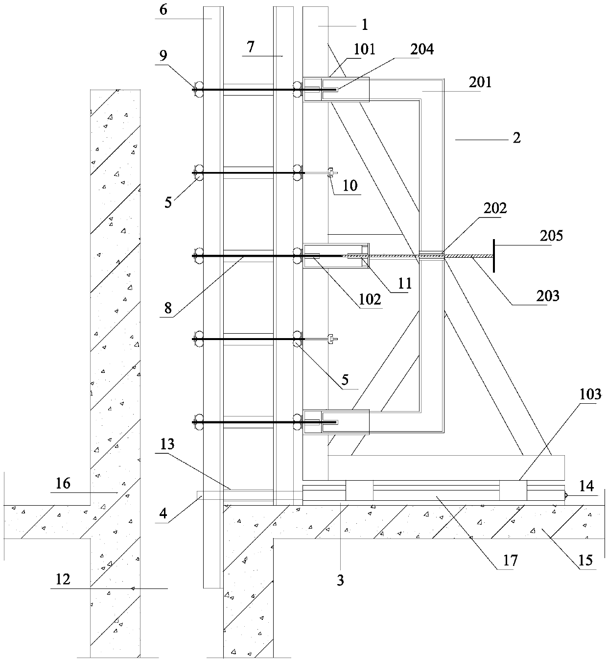
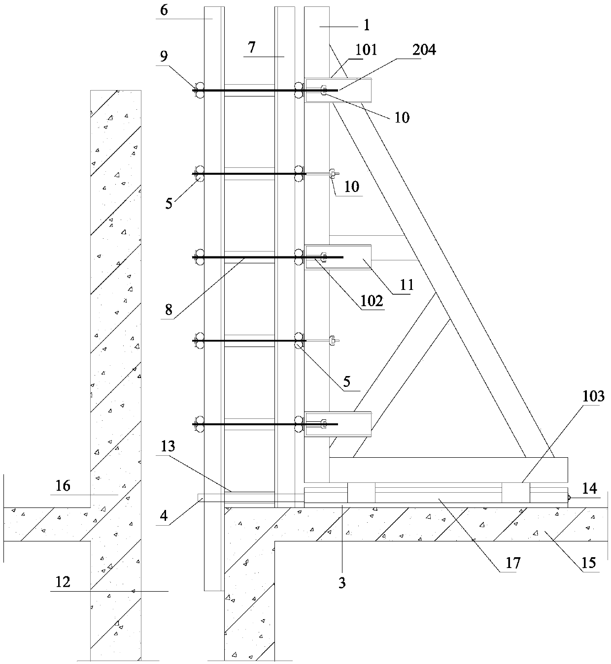
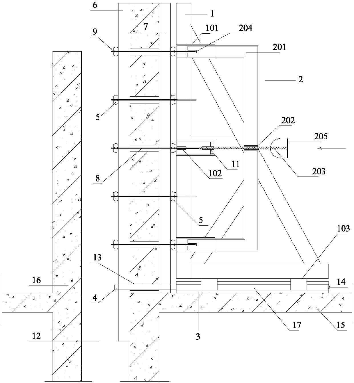
[0038] The present invention will be further described in detail below with reference to the accompanying drawings and examples. The following examples are explanations of the present invention and are not limited to the following examples. In the construction of shear wall formwork engineering in the post-deformation joint section of a high-rise building structure, the sliding and pushing-type installation and removal formwork support system and construction method of the post-deformation joint section shear wall are adopted.

[0039] Such as figure 1 , figure 2 As shown, the sliding and pushing type installation and dismantling formwork support system of the shear wall in the post-deformation joint section of the present invention includes a sliding single-sided bracket 1, a screwing and pushing device 2, a sliding guide rail 3, a supporting steel pipe 4, and an inner Template 6, outer template 7, pull screw 8; three guiding steel pipes 101 are arranged on the sliding type...


PUM


Abstract

The invention relates to a deformation joint post-section shear wall sliding-pushing type installation and disassembling template erection system and a construction method. The construction method comprises the main construction steps of: installing a sliding guide rail; installing a sliding type single-sided bracket; pushing off an inside template by utilizing a screwing pushing device; recovering the sliding type single-sided bracket; hanging an outside template away. According to the invention, the templates are supported by utilizing a supporting steel pipe extending out of the sliding guide rail, and the sliding type single-sided bracket and cross-pulling screws are combined so as to fix the templates; then by screwing the screwing pushing device and further pushing the cross-pullingscrews, the inside template is pushed away; finally, the sliding-type single-sided bracket is recovered and the outside template is hung away. According to the invention, components mostly are precastand recoverable; the template erection system is convenient to install and rapid in construction; meanwhile, a constructed shear wall is high in quality and high in template recyclability rate; problems of a great amount of consumables for installing and disassembling the templates, long period, easiness for damaging the templates and the shear wall and the like in the prior art are solved; the deformation joint post-section shear wall sliding-pushing type installation and disassembling template erection system and the construction method are obvious in economic beneficial effects.

Description

technical field [0001] The invention relates to a push-pull formwork support system and construction method for a shear wall with narrow deformation joints, which belongs to the field of construction engineering and is suitable for the construction of a shear wall formwork project in a post-deformation joint section of a high-rise building structure. Background technique [0002] In construction engineering, the installation method and quality control of the shear wall formwork in the rear section of the high-rise shear wall structure have always been difficult in construction. The traditional polystyrene board formwork method has the following problems: First, the side of the poured concrete will be The extrusion of the polystyrene board to the other side resulted in no protective layer for the reinforcement on the other side, and the polystyrene board could not be taken out, resulting in waste; second, due to the limitation of the existing shear wall in the previous section...

Claims


Application Information

Patent Timeline
IPC IPC(8): E04B2/56E04G11/06E04G11/08E04G11/20E04G19/00
CPCE04B2/56E04G11/06E04G11/08E04G11/20E04G19/00
Inventor 陈小林朱凯张迎珍
Owner 杭州昂创科技有限公司
Why Eureka
Try Eureka