
Draining self-adjusting rotary air heater and adjusting method thereof

A technology of automatic adjustment and adjustment method, applied in combustion methods, lighting and heating equipment, indirect carbon dioxide emission reduction, etc., can solve the problem of increasing the primary and secondary air side resistance of the boiler, the power consumption of the primary fan, the blower, and the steam consumption of the heater. and temperature changes, heat exchange elements cannot be moved, etc., to achieve the effect of high thermal energy utilization, saving plant electricity, and improving heat transfer temperature difference

Pending Publication Date: 2019-04-26
NORTHWEST ELECTRIC POWER DESIGN INST OF CHINA POWER ENG CONSULTING GROUP
View PDF0 Cites 0 Cited by
  • Summary
  • Abstract
  • Description
  • Claims
  • Application Information

AI Technical Summary

Problems solved by technology

[0003] The control method of conventional air heaters adopts steam inlet side adjustment and fixed installation of heat exchange elements. This design scheme has the following problems: 1) While adjusting the amount of heating steam, due to the decrease in the internal pressure of the air heater, its saturation The temperature also decreases accordingly, that is, the steam consumption and temperature of the air heater are changing synchronously; 2) In summer or under the high load condition of the boiler, the heat exchange element cannot be moved when the air heater is out of operation, which increases the operating time of the boiler. 1. Side resistance of secondary wind and power consumption of primary fan and blower

Method used


Image

  • Draining self-adjusting rotary air heater and adjusting method thereof
  • Draining self-adjusting rotary air heater and adjusting method thereof
  • Draining self-adjusting rotary air heater and adjusting method thereof

Examples


Embodiment Construction

[0019] The present invention will be described in further detail below in conjunction with the accompanying drawings.

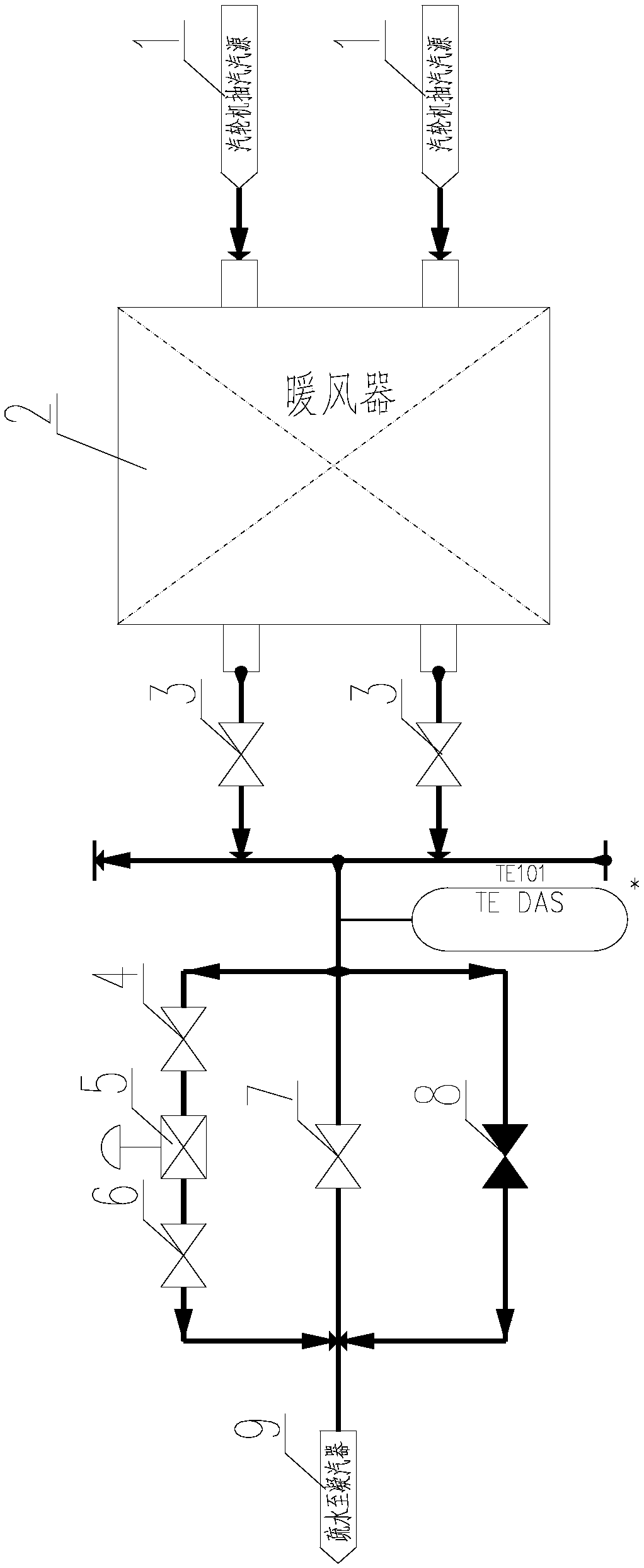
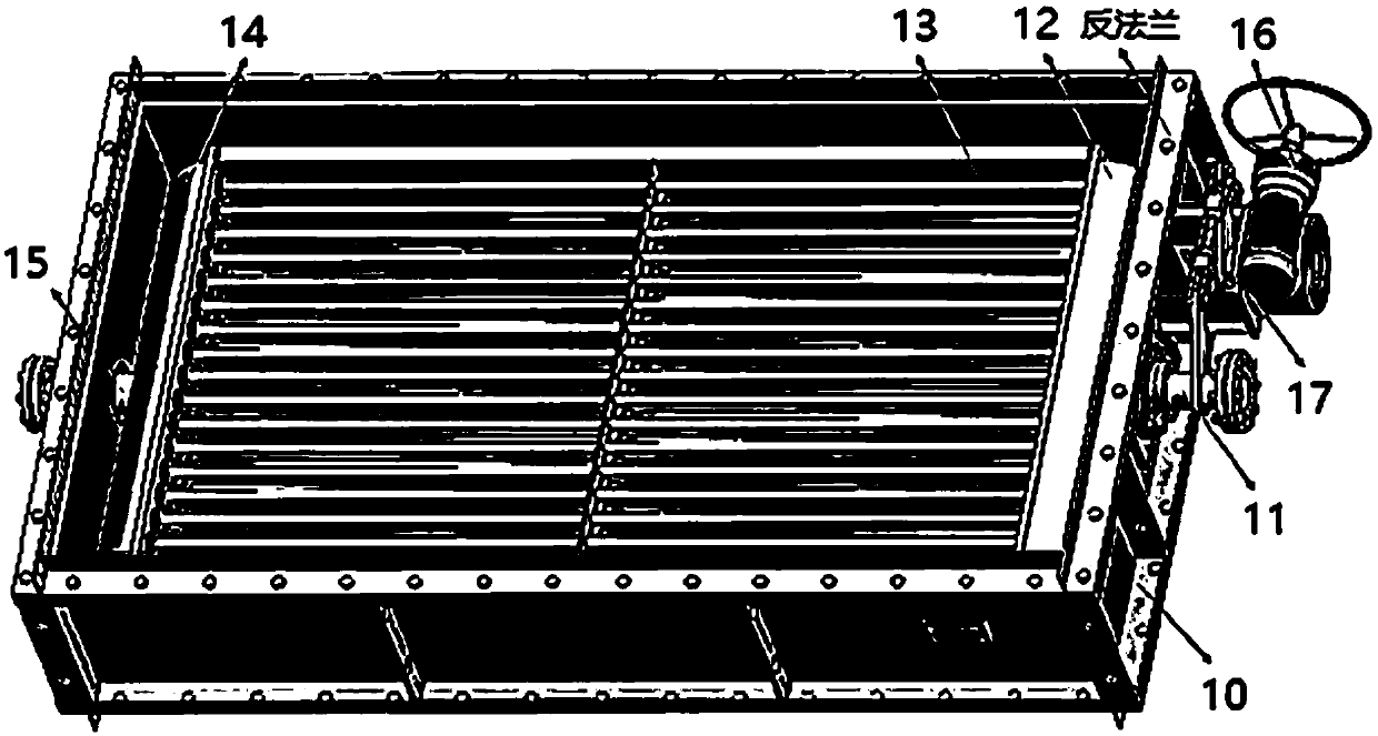
[0020] see Figure 1-2 , the rotary air heater with automatic adjustment of the hydrophobic side of the present invention structurally includes a housing 10, a steam inlet pipe 11, a steam inlet pipe box 12, a finned tube 13, a drain pipe box 14, a drain pipe 15, and a reducer 16 And the link mechanism 17.

[0021] The heat exchange element of the air heater is arranged in the housing 10, one end of the heat exchange element of the air heater is connected to the steam inlet pipe 11, and the other end is connected to the drain pipe 15; The heat exchange element of the fan rotates between 0° and 90°. There are station pointers and dials on the surface of the reducer 16. When the station pointer points to 0° of the dial, it means that the heater is in working condition. When the pointer points to 90° of the dial, it means the heater is not working.

[0022] T...


PUM


Abstract

The invention relates to a draining self-adjusting rotary air heater and an adjusting method thereof. The air heater comprises an adjusting valve assembly and a rotary mechanism, wherein the adjustingvalve assembly is arranged on a draining pipeline of the air heater, and the rotary mechanism is used for changing the direction of a heat exchange element of the air heater; one end of the heat exchange element of the air heater is connected with a steam inlet pipe, and the other end of the heat exchange element of the air heater is connected with a drain pipe; the rotary mechanism comprises a speed reducer, and the heat exchange element of the air heater is driven to rotate between 0 degree and 90 degrees by the speed reducer by virtue of a linkage mechanism; and the adjusting valve assembly comprises a manual stop valve and a pneumatic adjusting valve which are arranged on a draining outlet pipeline of the air heater, and the pneumatic adjusting valve is used for adjusting the water level in the air heater by using the metal wall temperature of the cold end of an air preheater as an adjusting signal. The draining self-adjusting rotary air heater is favorable for increasing the heattransfer temperature difference, reducing the heat exchange area of the air heater and reducing the manufacturing cost. When the air heater is stopped, the heat exchange element is rotated in the direction of airflow, so that the wind resistance of a boiler can be reduced, and auxiliary power is saved.

Description

technical field [0001] The invention relates to a boiler auxiliary machine, in particular to a rotary air heater with automatic adjustment on the hydrophobic side and an adjustment method thereof. Background technique [0002] Power plant boilers generally use heaters to preheat the air temperature to solve the problem of low-temperature corrosion on the heating surface of the boiler tail during winter and low-load operation of the unit. Preheat the low-temperature air to increase the metal wall temperature of the heating surface at the rear of the boiler, and usually take the metal wall temperature of the cold end of the air preheater as the adjusted value. [0003] The control method of conventional air heaters adopts steam inlet side adjustment and fixed installation of heat exchange elements. This design scheme has the following problems: 1) While adjusting the amount of heating steam, due to the decrease in the internal pressure of the air heater, its saturation The te...

Claims


Application Information

Patent Timeline
Patent Type & Authority Applications(China)
IPC IPC(8): F23L15/00
CPCF23L15/00Y02E20/34
Inventor 王宏明郑烨周朝辉宋江文
Owner NORTHWEST ELECTRIC POWER DESIGN INST OF CHINA POWER ENG CONSULTING GROUP
Learn More