Annular fixed bed combustion furnace applied to powder materials

A technology of annular furnace and fixed bed, applied in fluidized bed furnaces, furnaces, furnace types, etc., can solve the problems of not meeting quality requirements, narrow application surface, complex furnace structure, etc., achieving simple structure, long service life, The effect of large output adjustment

Inactive Publication Date: 2019-04-16
WUHAN UNIV OF SCI & TECH
View PDF9 Cites 1 Cited by
  • Summary
  • Abstract
  • Description
  • Claims
  • Application Information

AI Technical Summary

Problems solved by technology

[0005] The above-mentioned existing furnaces have complex structures and narrow application areas, and are only suitable for biomass fuels that have not been pyrolyzed, and are not suitable for fuels with relatively low carbon content after pyrolysis
For example, for some special powder material production processes, it is required that the carbon content in the ash of the powder material after combustion is less than 1%. The fluidized bed combustion system and the above two biomass combustion furnaces obviously do not meet the quality requirements of this type of product

Method used


Image

  • Annular fixed bed combustion furnace applied to powder materials
  • Annular fixed bed combustion furnace applied to powder materials

Examples


Embodiment 1

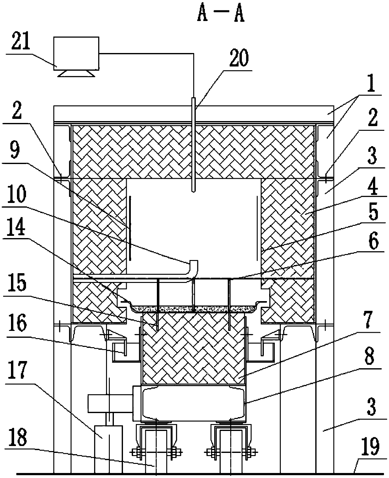
[0024] Embodiment 1: The present invention provides a kind of annular fixed-bed combustion furnace that is applied to powder material, and its structure is as follows figure 1 , 2 shown. figure 1 For the top view of the combustion furnace, from figure 1 It can be seen that the overall structure of the combustion furnace of the present invention is an annular furnace of continuous production type. On the figure, it can be seen that the annular combustion furnace is provided with an annular furnace cover, and the body of furnace and the bottom of the furnace under the furnace cover are also annular. figure 1 There is a material inlet on the left side of the middle combustion furnace, and a distributing machine 11 is provided, and there is an outlet on the right side, and a discharge machine 12 is provided. There is a smoke exhaust device 13 on the right side of the discharge machine, and the smoke generated by the material combustion is produced. Smoke exhaust device exhaust. ...


PUM


Abstract

The invention relates to an annular fixed bed combustion furnace applied to powder materials. The annular fixed bed combustion furnace applied to the powder materials is provided with a furnace cover,a furnace body, a furnace bottom, an inner lining plate, a heating electric heat body, a combustion-supporting air system, a material tray, a water seal device, a transmission system, a distributingmachine, a discharging machine, a smoke exhaust device, a detection system and a control system. The furnace bottom is concentric with the furnace body, and the inner lining plate covers the inner side of the furnace body; the material tray is fixed to the furnace bottom; the part between the furnace body and the furnace bottom is sealed by the water seal device, and the furnace bottom rotates around a central axis under the action of the transmission system; the powder materials are distributed onto the material tray under the action of the distributing machine and enter a furnace driven by rotating the furnace bottom; air is blown into the furnace by the combustion-supporting air system, and the powder materials and the air are heated by the heating electric heat body until combustion reaction is started; and the smoke generated by combustion is emitted from the smoke exhaust device, the powder materials enter the furnace from an inlet for operation and complete combustion, and are sent out by the discharging machine from an outlet. The combustion furnace has a simple structure, stable movement process, low manufacturing cost, simple and convenient construction and maintenance, and long service life.

Description

technical field [0001] The invention relates to a powder material combustion furnace, in particular to an annular fixed bed combustion furnace applied to powder materials. Background technique [0002] In the field of powder material combustion, circulating fluidized bed is a relatively mature technology for clean powder material combustion. It has outstanding advantages such as wide material adaptability, high combustion efficiency, low nitrogen oxide emissions, large load adjustment ratio and fast load adjustment. When the powder material is burned in the fluidized bed, it is in a flowing state driven by the high-speed combustion-supporting air, and the flow rate is higher than 4m / s, even reaching 8m / s. The residence time of the powder material in the fluidized bed is relatively short. Therefore, materials must undergo circulating fluidized combustion to achieve high combustion efficiency. Taking coal powder as an example, the carbon content in the ash after combustion exc...

Claims


Application Information

Patent Timeline
Patent Type & Authority Applications(China)
IPC IPC(8): F27B15/00F27B15/04F27B15/08F27B15/14
CPCF27B15/00F27B15/04F27B15/08F27B15/14
Inventor 潘妮高标付继江戴方钦
Owner WUHAN UNIV OF SCI & TECH
Why Eureka
Try Eureka