Extracting device and method of microplastics in soil

An extraction device and technology for microplastics, which are used in chemical instruments and methods, preparation of samples for testing, solid separation, etc., can solve the problems of in-depth development of pollution research, restricting microplastics, etc., to shorten the separation time, easy to operate, and save money. human effect

Active Publication Date: 2019-04-26
HENAN UNIVERSITY
View PDF8 Cites 12 Cited by
  • Summary
  • Abstract
  • Description
  • Claims
  • Application Information

AI Technical Summary

Problems solved by technology

Therefore, in the research on soil microplastics, there is still no efficient and accurate method to separate them from the soil, which seriously restricts the in-depth research on microplastic pollution.

Method used


Image

  • Extracting device and method of microplastics in soil
  • Extracting device and method of microplastics in soil
  • Extracting device and method of microplastics in soil

Examples


Embodiment 1

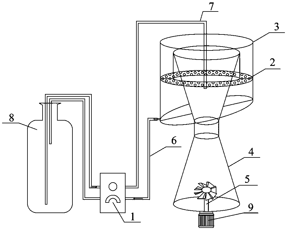
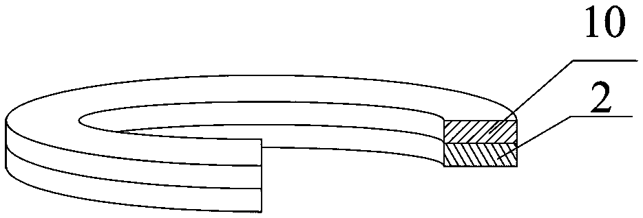
[0036] like Figure 1 to Figure 3As shown, an extraction device for microplastics in soil includes a separation tank 4, a liquid storage tank 8 and a liquid return tank 3, and a liquid inlet pipe 7 is arranged between the liquid storage tank 8 and the separation tank 4, and the liquid return A liquid outlet pipe 6 is provided between the pool 3 and the liquid storage tank 8, and a peristaltic pump 1 is provided on the liquid inlet pipe 7 and the liquid outlet pipe 6. The peristaltic pump 1 is a multi-channel peristaltic pump 1, and the separation pool 4 and the liquid return pool A layer of filter assembly is arranged between 3, and the filter assembly includes a ring screen 2 and a filter membrane 10, and the filter membrane 10 is arranged on the ring screen 2; The bottom of the separation tank 4 is provided with a stirrer 5 to stir The device 5 is connected to the motor 9 . Described separation pond 4 comprises upper round table and lower round table, and the height of desc...

Embodiment 2

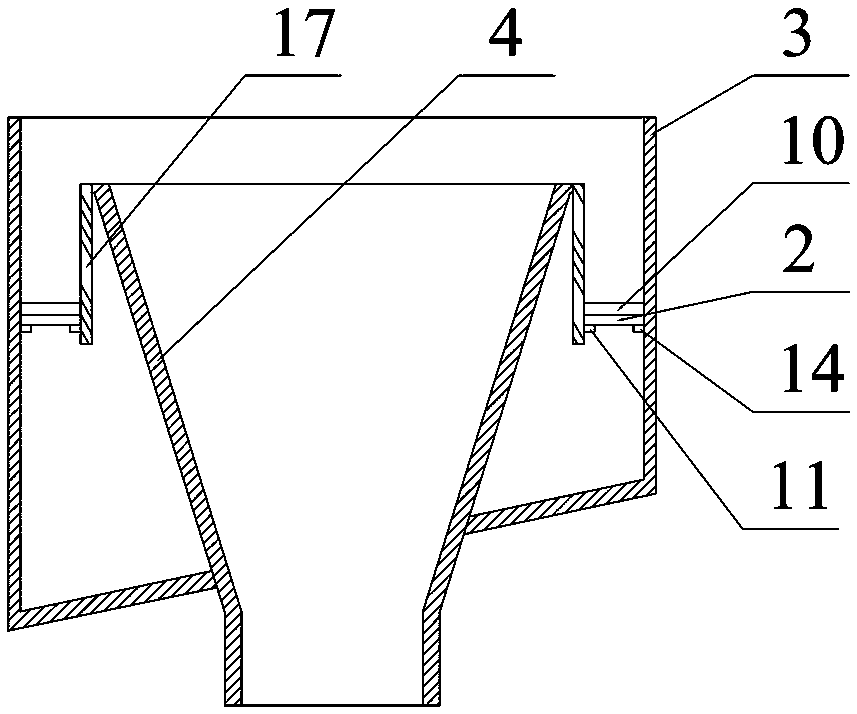
[0040] like figure 1 , Figure 4 and Figure 5 As shown, it is basically the same as Example 1, except that the angle between the bottom surface of the liquid return tank 3 and the horizontal plane is 45°, the filter assembly is two layers, and the two layers of filter assemblies are distributed up and down, and the separation tank 4 The upper outer wall is provided with a circular column 17, and the filter assembly of each layer is lapped between the circular column 17 and the liquid return tank 3 through the lap joint assembly (the filter assembly and the outer wall of the circular column 17 and the inner wall of the liquid return tank 3 can be Sealing is achieved by arranging existing structures such as rubber pads), the lap assembly includes a first fixing bar 11 and a second fixing bar 14, the first fixing bar 11 is evenly arranged on the outer wall of the circular column 17, and the second fixing bar 11 The bars 14 are evenly arranged on the inner wall of the liquid re...

Embodiment 3

[0043] like figure 1 and Image 6 As shown, it is basically the same as Example 1, except that the angle between the bottom surface of the liquid return tank 3 and the horizontal plane is 15°, the filter assembly is two layers, and the two layers of filter assemblies are distributed up and down, and the separation tank 4 The upper outer wall is provided with a circular column 17, and the filter assembly of each layer is lapped between the circular column 17 and the liquid return tank 3 through the lap joint assembly (the filter assembly and the outer wall of the circular column 17 and the inner wall of the liquid return tank 3 can be Sealing is achieved by arranging existing structures such as rubber pads), the lap assembly includes a first fixing bar 11 and a second fixing bar 14, the first fixing bar 11 is arranged in the outer wall of the circular column 17 and is connected with the circular ring The column 17 is rotatably connected, and the specific implementation is as f...


PUM

PropertyMeasurementUnit
densityaaaaaaaaaa

Abstract

The invention provides an extracting device and method of microplastics in soil. The device comprises a separation pool, a liquid storage tank and a liquid return pool, a liquid inlet pipe is arrangedbetween the liquid storage tank and the separation pool, a liquid outlet pipe is arranged between the liquid return pool and the liquid storage tank, and a peristaltic pump is arranged on a pipelineof the liquid inlet pipe and the liquid outlet pipe; at least one layer of filtering assembly is arranged between the separation pool and the liquid return pool and comprises an annular sifting net and a filtering membrane, the filtering membrane is arranged on the annular sifting net, and a stirring device is arranged at the bottom of the separation pool. By means of the extracting device and method, a flotation liquid is utilized, microplastic particles which have low density and are mixed in the soil can be suspended on an upper solution layer, namely a non-settling layer, heavy sediment isstill at a bottom solution layer, namely a settling layer, and then by continuously adding the flotation liquid, the solution in the separation pool overflows, the microplastic particles suspended atthe non-settling layer overflow to the filtering sifting net along with the solution and are isolated by the filtering membrane on the filtering sifting net, and thus the purpose of separation is achieved. The device is simple and easy to operate, the separation time is short, and the separation effect is good.

Description

technical field [0001] The invention relates to the technical field of solid waste treatment, in particular to an extraction device and an extraction method for microplastics in soil. Background technique [0002] The advent of plastic has changed our way of life. Due to its ability to be used in a wide temperature range, low thermal conductivity, high strength-to-weight ratio, biological inertness, durability and other advantages, this material has been widely used all over the world, ranging from Household products to personal hygiene products, from clothing, packaging to building materials, plastic products appear in all aspects of human life. It is precisely because of its extensive use that since it was put into mass production in the 1950s, the world's plastic production has shown a rise. The trend of exponential growth has risen from 5 million tons in the 1950s to 322 million tons in 2016. [0003] While enjoying the convenience of plastic products to life, people a...

Claims


Application Information

Patent Timeline
Patent Type & Authority Applications(China)
IPC IPC(8): G01N1/28B03D1/00B01D61/00C02F1/44
CPCB01D61/00B03D1/00C02F1/44G01N1/28
Inventor 张成丽张伟平周艳梅陈志凡任少云钱静马建华
Owner HENAN UNIVERSITY
Why Eureka
Try Eureka