Device for generating excitation signal of crystal oscillator, chip, and crystal oscillator excitation system

A technology for generating a device and an excitation signal, applied in the electronic field, can solve the problems that the start-up time cannot meet the requirements of the chip, reduce the start-up time of the target crystal oscillator, and cannot be used.

Active Publication Date: 2019-04-26
北京昂瑞微电子技术股份有限公司
View PDF5 Cites 0 Cited by
  • Summary
  • Abstract
  • Description
  • Claims
  • Application Information

AI Technical Summary

Problems solved by technology

[0003] Generally, the start-up time cannot meet the needs of the chip. At present, the method to reduce the start-up time is: when the chip needs a clock signal of the target resonant frequency, output a clock signal close to the target resonant frequency to the target crystal oscillator used to provide the target resonant frequency. Excitation signal to increase the signal energy of the target crystal oscillator, thereby reducing the start-up time of the target crystal oscillator; in practical applications, the excitation signal can be an oscillating signal. The error between the frequency of the signal and the target resonance frequency is less than 0.5%; therefore, a device for generating an oscillating signal whose frequency meets the error requirement needs to be installed in the chip
[0004] At this time, because the device needs to generate a signal whose frequency meets the error requirements, the manufacturing process requirements for the device are relatively high; and once the device for reducing the start-up time of the target crystal oscillator is installed in the chip; in order to achieve fast start-up On the premise of vibration, the chip can only use the crystal oscillator whose frequency is within the error range including the target resonance frequency, but cannot use the crystal oscillator whose frequency is outside the error range including the target resonance frequency, that is, on the premise of achieving fast start-up, the chip can The crystal oscillator used is limited

Method used


Image

  • Device for generating excitation signal of crystal oscillator, chip, and crystal oscillator excitation system
  • Device for generating excitation signal of crystal oscillator, chip, and crystal oscillator excitation system
  • Device for generating excitation signal of crystal oscillator, chip, and crystal oscillator excitation system

Examples


Embodiment Construction

[0038] The following will clearly and completely describe the technical solutions in the embodiments of the application with reference to the drawings in the embodiments of the application. Apparently, the described embodiments are only some of the embodiments of the application, not all of them. Based on the embodiments in this application, all other embodiments obtained by persons of ordinary skill in the art without making creative efforts belong to the scope of protection of this application.

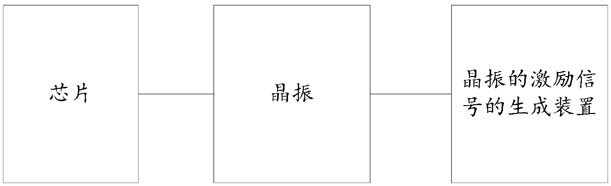
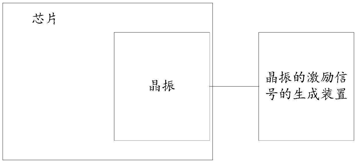
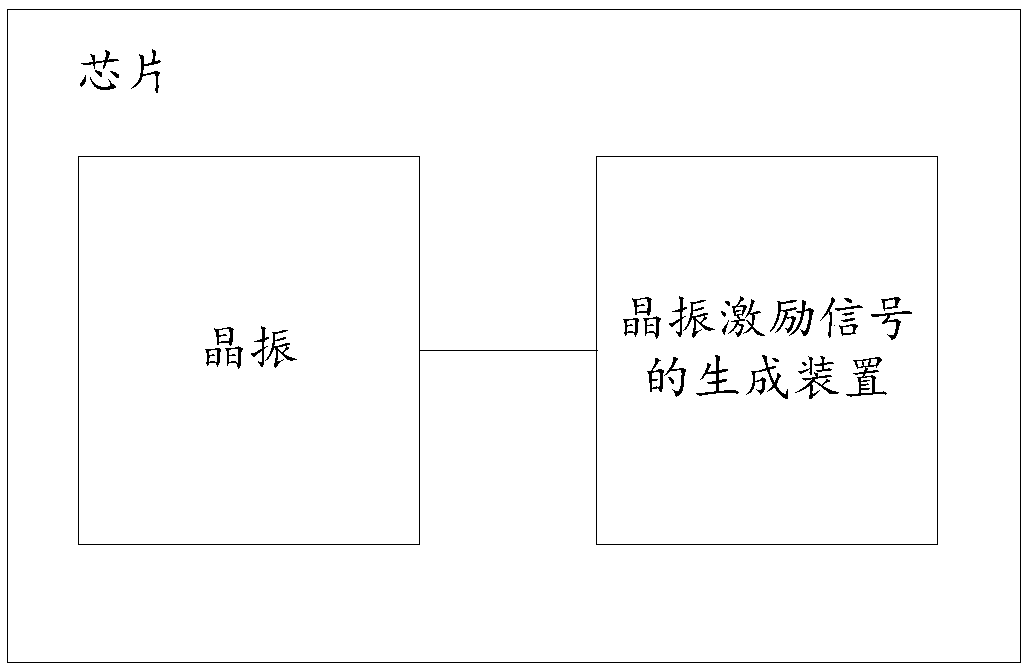
[0039] FIG. 1 is an example diagram of an application scenario of the device for generating an excitation signal for a crystal oscillator provided by the present application, including the device for generating an excitation signal for a crystal oscillator provided by the present invention, a chip and a crystal oscillator in the prior art. Wherein, the crystal oscillator is respectively connected with the generator of the excitation signal of the crystal oscillator and the chip; wher...


PUM


Abstract

The application discloses a device for generating an excitation signal of a crystal oscillator, a chip, and a crystal oscillator excitation system. The device for generating an excitation signal of acrystal oscillator comprises: a clock signal generator and a sigma delta modulator, wherein the clock signal generator is connected to the sigma delta modulator; the clock signal generator is used forgenerating a clock signal of a target frequency, and the target frequency is a frequency of a preset range centered at twice the target resonance frequency; and the sigma delta modulator is used forgenerating quantization noise based on the clock signal, and the quantization noise is used as an excitation signal. With the embodiment of the application, on the premise of achieving fast start-up,the degree of crystal oscillator that can be used by the chip is reduced, and the error tolerance to the manufacturing process of the device is increased.

Description

technical field [0001] The present application relates to the field of electronic technology, and in particular to a device for generating an excitation signal of a crystal oscillator, a chip, and a crystal oscillator excitation system. Background technique [0002] The execution of all instructions in the chip needs to be based on a clock signal. The clock signal is generally provided by a Quartz Crystal Oscillator. The time required for the crystal oscillator to generate the clock signal from receiving the start-up instruction of the chip is called the start-up time. [0003] Generally, the start-up time cannot meet the needs of the chip. At present, the method to reduce the start-up time is: when the chip needs a clock signal of the target resonant frequency, output a clock signal close to the target resonant frequency to the target crystal oscillator used to provide the target resonant frequency. Excitation signal to increase the signal energy of the target crystal osci...

Claims


Application Information

Patent Timeline
Patent Type & Authority Applications(China)
IPC IPC(8): H03M3/00
CPCH03M3/344Y02D30/70
Inventor 周晓秋钱永学孟浩叶晓斌黄鑫
Owner 北京昂瑞微电子技术股份有限公司
Why Eureka
Try Eureka