Glass chamfering machine

A chamfering machine and glass technology, applied in the direction of grinding frame, grinding machine parts, machine tools suitable for grinding workpiece edges, etc., can solve the problem of corrosion of screw parts, affecting the working stability of the glass chamfering machine, It is not easy to maintain and repair problems, and achieve the effect of easy maintenance and repair

Pending Publication Date: 2019-05-03
东莞市众度机械设备有限公司
View PDF0 Cites 5 Cited by
  • Summary
  • Abstract
  • Description
  • Claims
  • Application Information

AI Technical Summary

Problems solved by technology

Since the X-axis drive mechanism and the Z-axis drive mechanism are exposed outside the frame, and a large amount of water is used in glass processing, the water splashes on the X-axis drive mechanism and the Z-axis drive mechanism, causing screw rods, slide rails and other components to Corrosion affects the working stability of the glass chamfering machine; in addition, it is not easy to maintain and repair

Method used


Image

  • Glass chamfering machine
  • Glass chamfering machine
  • Glass chamfering machine

Examples


Embodiment Construction

[0034] The present invention will be further described below in conjunction with the examples, which are preferred embodiments of the present invention.

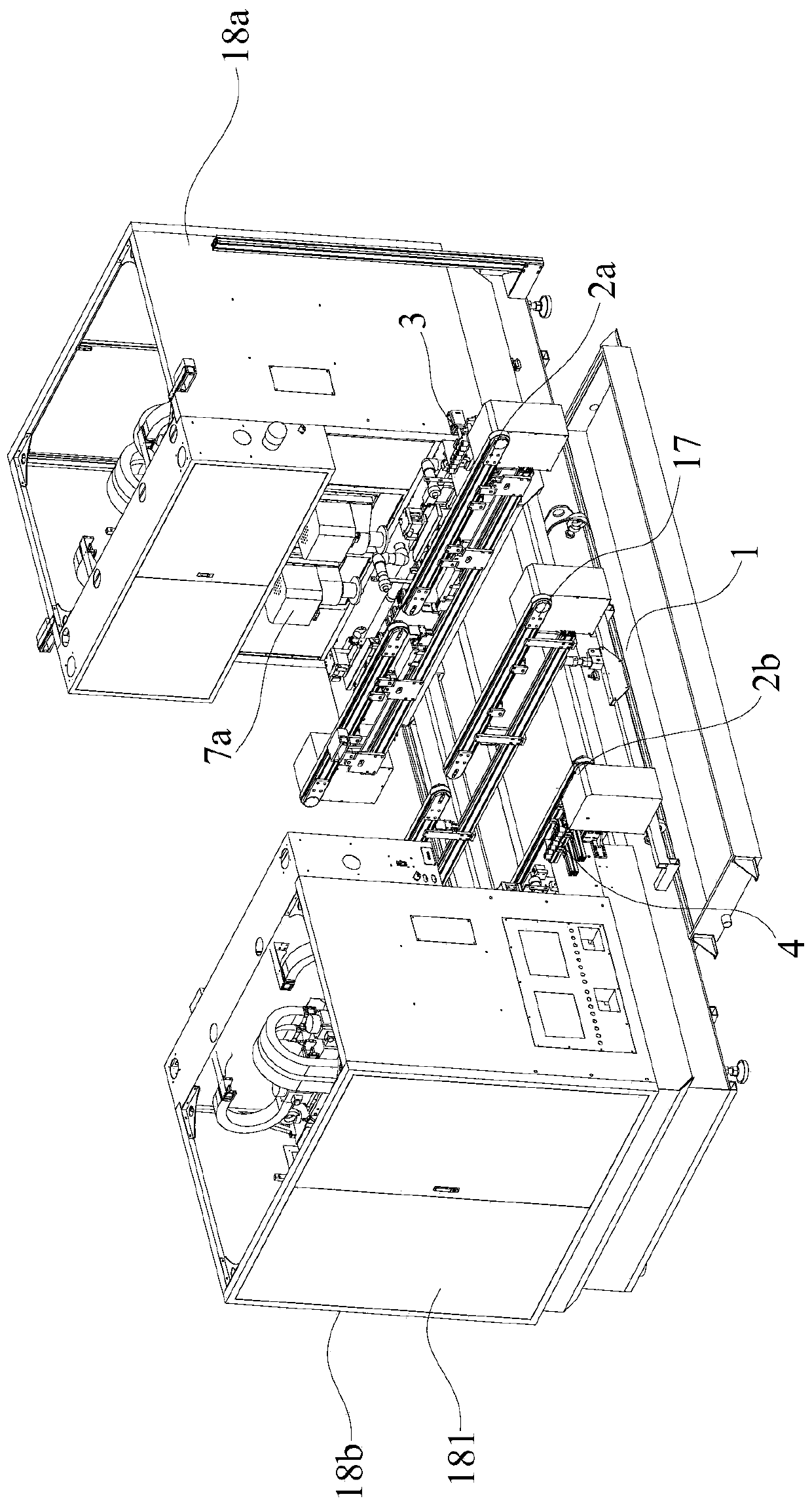
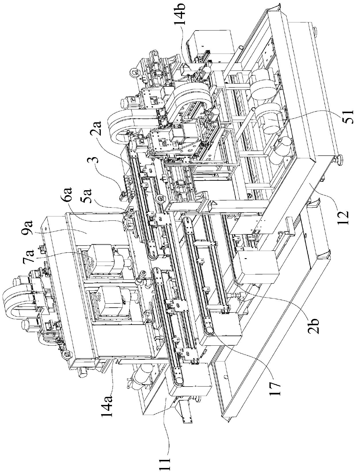
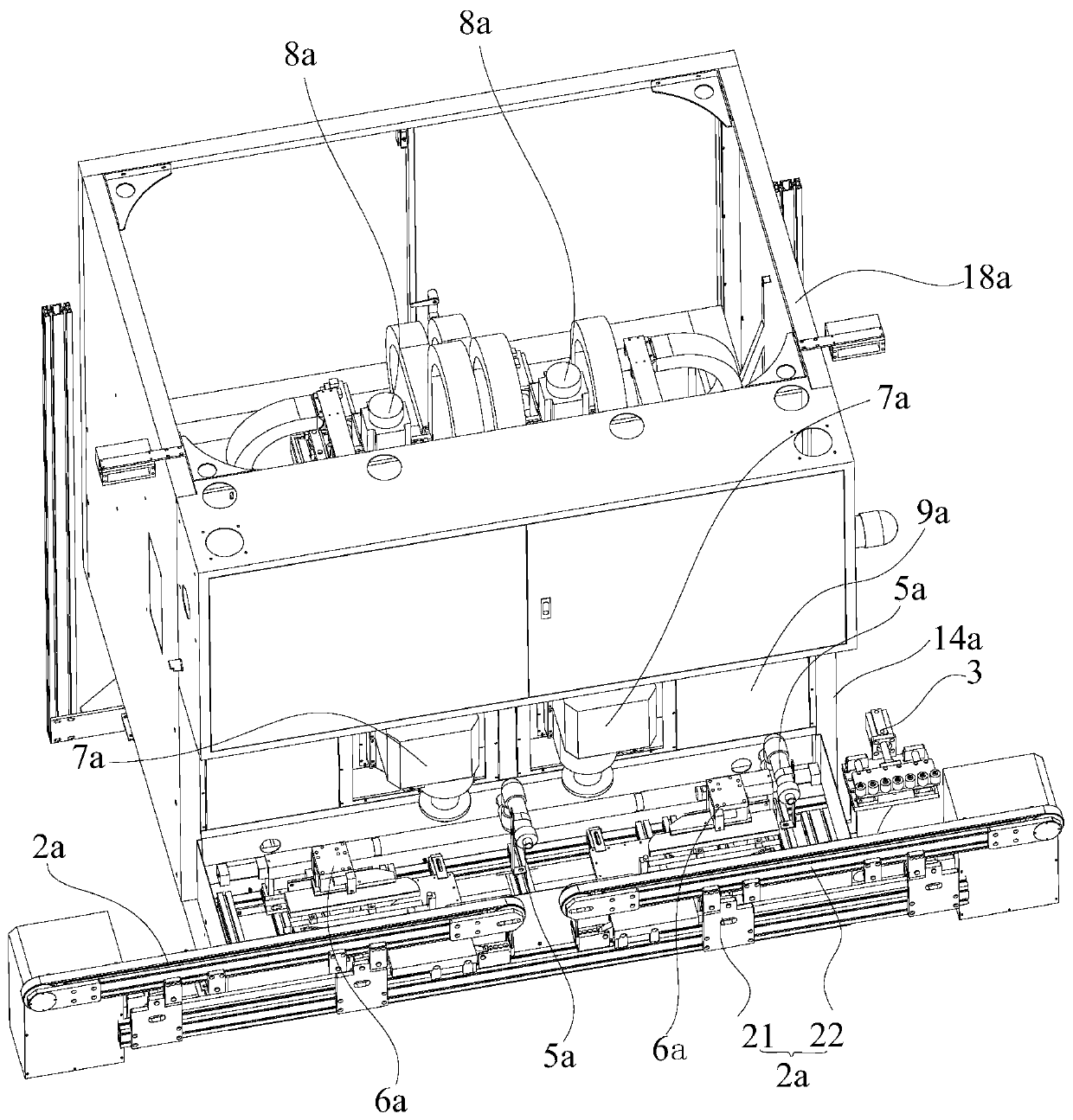
[0035] Such as Figure 1-16 As shown, a glass chamfering machine includes a base 1 and a driving frame 11 and a driven frame 12 that are relatively arranged on the base 1, and the driving frame 11 is driven by a frame driving mechanism 13 It is close to or far from said driven frame 12 . The driving frame 11 and the driven frame 12 are respectively provided with several liftable conveyor belt mechanisms 2a and 2b, and the conveyor belt mechanisms 2a and 2b transport glass along the X-axis direction. The feeding end of the conveyor belt mechanism 2a on the active frame 11 is provided with an active positioning device 3 . A driven positioning device 4 is provided at the feeding end of the conveyor belt mechanism 2 b on the driven frame 12 . Air blowing devices 5a and 5b and glass clamping and positioning devices 6a and 6b a...


PUM


Abstract

The invention discloses a glass chamfering machine. The glass chamfering machine comprises a machine base, a driving rack and a driven rack, wherein the driving rack and the driven rack are arranged on the machine base oppositely; the driving rack is driven by a rack driving mechanism to get close to or get away from the driven rack; the driving rack and the driven rack are each provided with a plurality of lifting conveying belt mechanisms, and driving positioning devices are arranged at the feeding ends of the conveying belt mechanisms on the driving rack; driven positioning devices are arranged at the feeding ends of the conveying belt mechanisms on the driven rack; air blowing devices and glass clamping positioning devices are sequentially arranged on the outer sides of the conveying belt mechanisms correspondingly; mounting brackets extending in the vertical directions are further arranged on the driving rack and the driven rack correspondingly; and one or more sets of three-axismoving mechanisms used for driving a main shaft device to move in the X, Y and Z axis directions are arranged on the outer sides of the mounting brackets correspondingly. The main shaft device and thethree-axis moving mechanisms are located on the two sides of a waterproof cover body correspondingly, the waterproof cover body achieves the waterproof action, and the purposes of proofing water andrust and facilitating maintenance and repair are achieved.

Description

technical field [0001] The invention relates to the technical field of glass processing equipment, in particular to a glass chamfering machine. Background technique [0002] The glass chamfering machine is a kind of CNC machine tool. The glass chamfering machine is mainly used in the fine processing of various glasses, special-shaped cutting and other processing procedures. [0003] The glass chamfering machine has an X-axis drive mechanism, a Y-axis drive mechanism and a Z-axis drive mechanism. The above-mentioned mechanisms are used to drive the main shaft to move along the X, Y, and Z axes. In a traditional glass chamfering machine, the main shaft device is installed on the Z-axis drive mechanism, the Z-axis drive mechanism is installed on the X-axis drive mechanism, and the X-axis drive mechanism is installed on the Y-axis drive mechanism. Most of the above-mentioned drive mechanisms include components such as screw rods and slide rails. Since the X-axis drive mechanis...

Claims


Application Information

Patent Timeline
Patent Type & Authority Applications(China)
IPC IPC(8): B24B9/08B24B41/00B24B41/02B24B41/06B24B47/12B24B53/06B24B55/00
Inventor 刘治业刘再奇陈晓东
Owner 东莞市众度机械设备有限公司
Why Eureka
Try Eureka