High-voltage electrified aerial bare conducting wire lifting crane and rubber coating spray painting robot thereof

A technology of spraying robots and high-voltage electrification, which is applied to overhead lines/cable equipment, coatings, clockwork mechanisms, etc., can solve problems such as potential safety hazards, and achieve the effect of simple operation

Active Publication Date: 2019-05-03
重庆洎皋电力科技有限责任公司
View PDF6 Cites 4 Cited by
  • Summary
  • Abstract
  • Description
  • Claims
  • Application Information

AI Technical Summary

Problems solved by technology

[0005] In view of this, in order to solve the problem of potential safety hazards in the way of conveying automatic spraying robots through the control system in the prior art, the present invention provides a high-voltage electrified overhead bare wire lifting crane and its rubber-covered spraying robot. The transmission speed of the rubber-coated spraying robot can be adjusted, and there is no potential safety hazard. The operator can complete the transportation of the whole rubber-coated spraying robot on the ground

Method used


Image

  • High-voltage electrified aerial bare conducting wire lifting crane and rubber coating spray painting robot thereof
  • High-voltage electrified aerial bare conducting wire lifting crane and rubber coating spray painting robot thereof
  • High-voltage electrified aerial bare conducting wire lifting crane and rubber coating spray painting robot thereof

Examples


Embodiment Construction

[0034] Preferred embodiments of the present invention will be described in detail below.

[0035] The reference signs in the drawings of the description include:

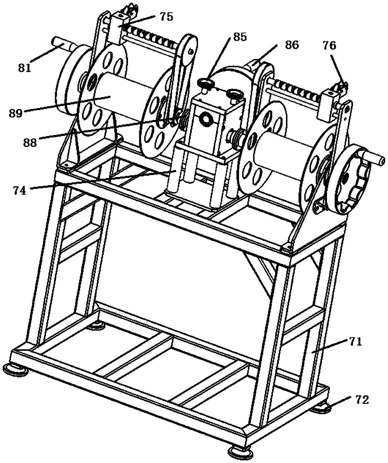
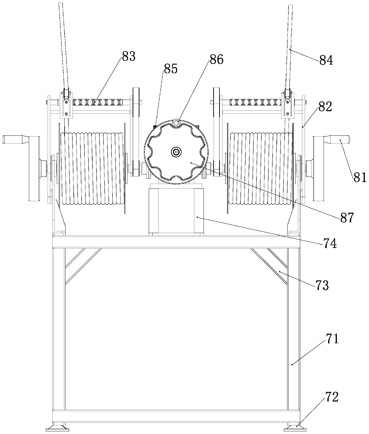
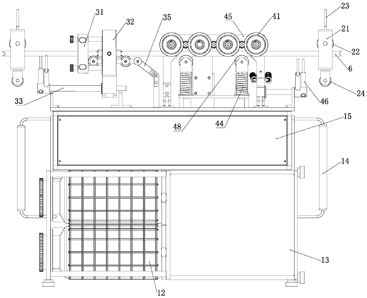
[0036] Cabinet 11, insulating paint bucket 12, sliding door 13, handle 14, motor box 15, locking block 21, third locking wheel 22, suspension ring 23, pulley 24, injection molding pressure ring 31, clamping arm 32, connecting rod 33. The first compression spring 34, the rotating arm 35, the first roller 36, the clamping block 37, the fixed rod 38, the pressure rod 39, the second locking wheel 41, the driven wheel 42, the conveyor belt 43, the second compression spring 44, Position plate 45, second rocker 46, gear 47, second roller 48, cleaning brush 5, bare wire 6, frame 71, supporting angle 72, reinforcing rib 73, support frame 74, slider 75, traction wheel 76 , the first handwheel 81, the support plate 82, the guide rod 83, the stay cord 84, the third handwheel 85, the second handwheel 86, the worm wheel 87, the ...


PUM


Abstract

The invention belongs to the technical field of electric power systems, and relates to a high-voltage electrified aerial bare conducting wire lifting crane and a rubber coating spray painting robot ofthe high-voltage electrified aerial bare conducting wire lifting crane. A lifting device in the lifting crane comprises a wire speed adjusting device and wire winding devices, wherein the wire speedadjusting device is installed in the middle of the upper end of a machine frame, and the wire winding devices are installed on the two sides of the wire speed adjusting device. The wire speed adjusting device comprises a supporting frame, a worm and a worm wheel, wherein the supporting frame is installed on the machine frame, the worm is arranged on the supporting frame, and the worm wheel mesheswith the worm. A second hand wheel is fixedly installed on the outer side of the worm wheel, and a plurality of third hand wheels are evenly and fixedly installed on the upper side of the worm wheel.Each wire winding device comprises a wire winding roller, a guide rod and a first hand wheel. The wire winding rollers are fixedly arranged at the free ends of the worm, the guide rods are fixedly arranged above the wire winding rollers, and the first hand wheels are installed on the outer sides of the wire winding rollers. Sliding blocks are arranged on the guide rod in a penetrative mode, and traction wheels are fixedly installed on the sliding blocks. Pull ropes which are used for lifting the rubber coating robot are wound around the wire winding rollers, and the free ends of the pull ropespass through the traction wheels. The problem that in the prior art, the potential safety hazard exists in the mode that an automatic spray painting robot is conveyed by a control system is solved.

Description

technical field [0001] The invention belongs to the technical field of electric power systems, and relates to a high-voltage live overhead bare wire lifting crane and a glue-covered spraying robot thereof, in particular to a live overhead bare-wire lifting crane and a glue-covered spraying robot suitable for high voltages of 10kv to 500kv . Background technique [0002] Insulation-coating robots are mainly used in the insulation treatment of bare wires in distribution overhead lines. The distribution network refers to the power supply network with a voltage level of 10kV-400V. At present, the urban distribution network is basically insulated, and more than 50% of the rural distribution network is still bare wires. Whenever it is windy and rainy, the distribution lines trip frequently, which affects the power supply efficiency and quality service. [0003] Over the years, the insulation transformation of distribution overhead lines and the local insulation of bare wires adja...

Claims


Application Information

Patent Timeline
Patent Type & Authority Applications(China)
IPC IPC(8): B66D1/74B66D1/04B66D1/26B66D1/20B66D1/38B05C5/02H02G1/02
Inventor 李国领孔维禅付恩勇周光文刘曙
Owner 重庆洎皋电力科技有限责任公司
Why Eureka
Try Eureka