Use method of scaffold in-situ fastening system

A kind of scaffolding and in-situ technology, which is applied to the accessories of scaffolding, building structure support, building structure support, etc., can solve the problems of difficult to guarantee the quality of stone curtain wall installation and high construction risk, so as to avoid flatness and transverse joints Deviation, avoid safety hazards, improve the effect of firmness

Inactive Publication Date: 2019-05-03
SHANGHAI BUILDING DECORATION ENG GRP
View PDF3 Cites 2 Cited by
  • Summary
  • Abstract
  • Description
  • Claims
  • Application Information

AI Technical Summary

Problems solved by technology

[0006] In view of the conflict between the location of the existing scaffolding wall parts and the installation position of the curtain wall unit plate, some curtain wall unit plates need to be installed after the scaffolding is removed, resulting in a relatively high construction risk and the problem that the installation quality of the stone curtain wall is difficult to guarantee , the object of the present invention is to provide a method for using the in-situ knotting system for scaffolding. The in-situ knotting device replaces the conventional knotting points of the scaffolding wall parts to the transverse direction between the pre-installed two adjacent curtain wall unit panels. The location of the joint avoids potential safety hazards and improves the firmness of the installation of the curtain wall unit panels; and the stone curtain wall can be installed sequentially from bottom to top, ensuring the flatness of the surface of the stone curtain wall and effectively controlling the width of the transverse joint

Method used


Image

  • Use method of scaffold in-situ fastening system
  • Use method of scaffold in-situ fastening system
  • Use method of scaffold in-situ fastening system

Examples


Embodiment Construction

[0041] The present invention will be described in further detail below in conjunction with the accompanying drawings and specific embodiments. It should be noted that all the drawings are in a very simplified form and use imprecise scales, and are only used to facilitate and clearly assist the purpose of illustrating the embodiments of the present invention. For the convenience of description, the "up" and "down" described below are consistent with the directions of up and down in the drawings, but this should not be a limitation of the technical solution of the present invention.

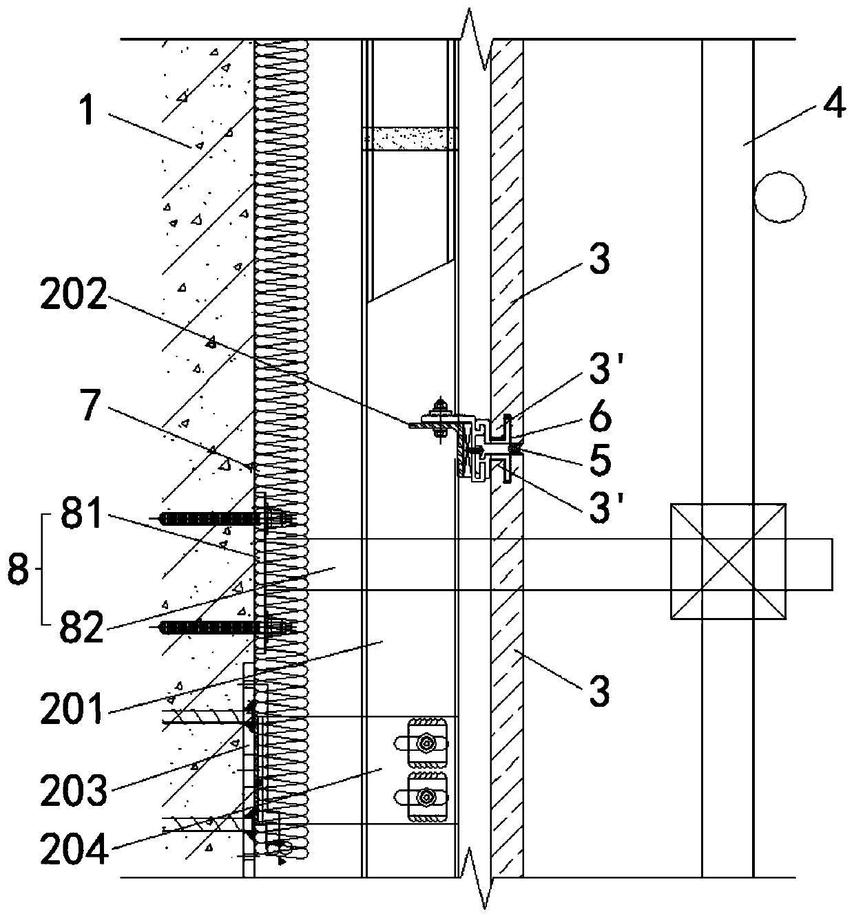
[0042] Combine below Figure 1 to Figure 17 Illustrate the usage method that utilizes scaffold in-situ tie-knot system of the present invention, concrete steps are as follows:

[0043] S1: if figure 1 As shown, a plurality of rear embedded parts 203 arranged according to the position of the pre-installed main keel 201 are anchored to the reinforced concrete beams and columns of the building exter...


PUM


Abstract

The invention discloses a use method of a scaffold in-situ fastening system, and relates to the technical field of stone curtain wall construction. The problems that the installation positions of scaffold wall connecting pieces and the installation positions of curtain wall unit plates conflict, the construction risks are high due to hole filling installation, and the installation quality is difficult to guarantee are solved. The use method comprises the following steps that the scaffold wall connecting parts are installed between the exterior wall of a building and scaffolds, and curtain wallunit plates are installed from bottom to top layer by layer; and when the scaffold wall connecting pieces are in a horizontal projection area of the preinstalled curtain wall unit plates, in-situ fastening devices replace the scaffold wall connecting pieces, the installation positions of the in-situ fastening devices corresponding to transverse joints are determined, anchoring parts are fixed, first fastening pieces are connected to the anchoring parts in a clamped mode, the other ends of the first fastening pieces penetrate through the transverse joints and extend to the outer side of a vertical face in which the curtain wall unit plates are located, one ends of second fastening pieces are connected to the extended ends of the first fastening pieces, and the other ends of the second fastening pieces are connected with the scaffolds; and the scaffold wall connecting pieces located in the horizontal projection area are removed, and the curtain wall unit plates are installed orderly.

Description

technical field [0001] The invention relates to the technical field of stone curtain wall construction, in particular to a method for using a scaffold in-situ knotting system. Background technique [0002] At present, scaffolding wall parts are usually used to connect the scaffolding to the main structure of the building to transmit the tension and pressure of the scaffolding. The setting of the scaffolding wall parts can strengthen the overall stability of the scaffolding, improve the bearing capacity of the scaffolding, and prevent the scaffolding from falling over. Or collapse and other major safety accidents. [0003] Such as figure 1 As shown, during the construction process of installing the stone curtain wall on the outside of the building base 1 and the insulation layer 7, due to the existence of the scaffold connecting wall 8, the curtain wall unit plate 3 located at the position of the scaffold connecting wall 8 is affected by it and cannot be normally pressed. O...

Claims


Application Information

Patent Timeline
Patent Type & Authority Applications(China)
IPC IPC(8): E04G21/00E04G5/04E04B2/88
Inventor 江旖旎刘少瑜徐永刚郭佳俊叶如楠浦聿聪
Owner SHANGHAI BUILDING DECORATION ENG GRP
Why Eureka
Try Eureka