Forced lubrication oil way system for engine

A lubricating oil circuit and engine technology, applied in the direction of engine lubrication, engine components, machines/engines, etc., can solve problems such as poor splash lubrication effect, and achieve the effect of good lubrication effect, improved performance, and prolonged service life.

Pending Publication Date: 2019-05-03
浙江康思特动力机械有限公司
View PDF6 Cites 5 Cited by
  • Summary
  • Abstract
  • Description
  • Claims
  • Application Information

AI Technical Summary

Problems solved by technology

[0004] In order to solve the problem of poor effect of forced lubrication and splash lubrication in the prior art, the present invention provides a forced lubrication system for the engine, which can make the internal moving parts get sufficient lubrication to the greatest extent, reduce the friction work of the engine, improve Engine power and service life

Method used


Image

  • Forced lubrication oil way system for engine
  • Forced lubrication oil way system for engine
  • Forced lubrication oil way system for engine

Examples


Embodiment 1

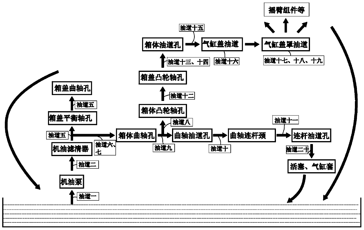
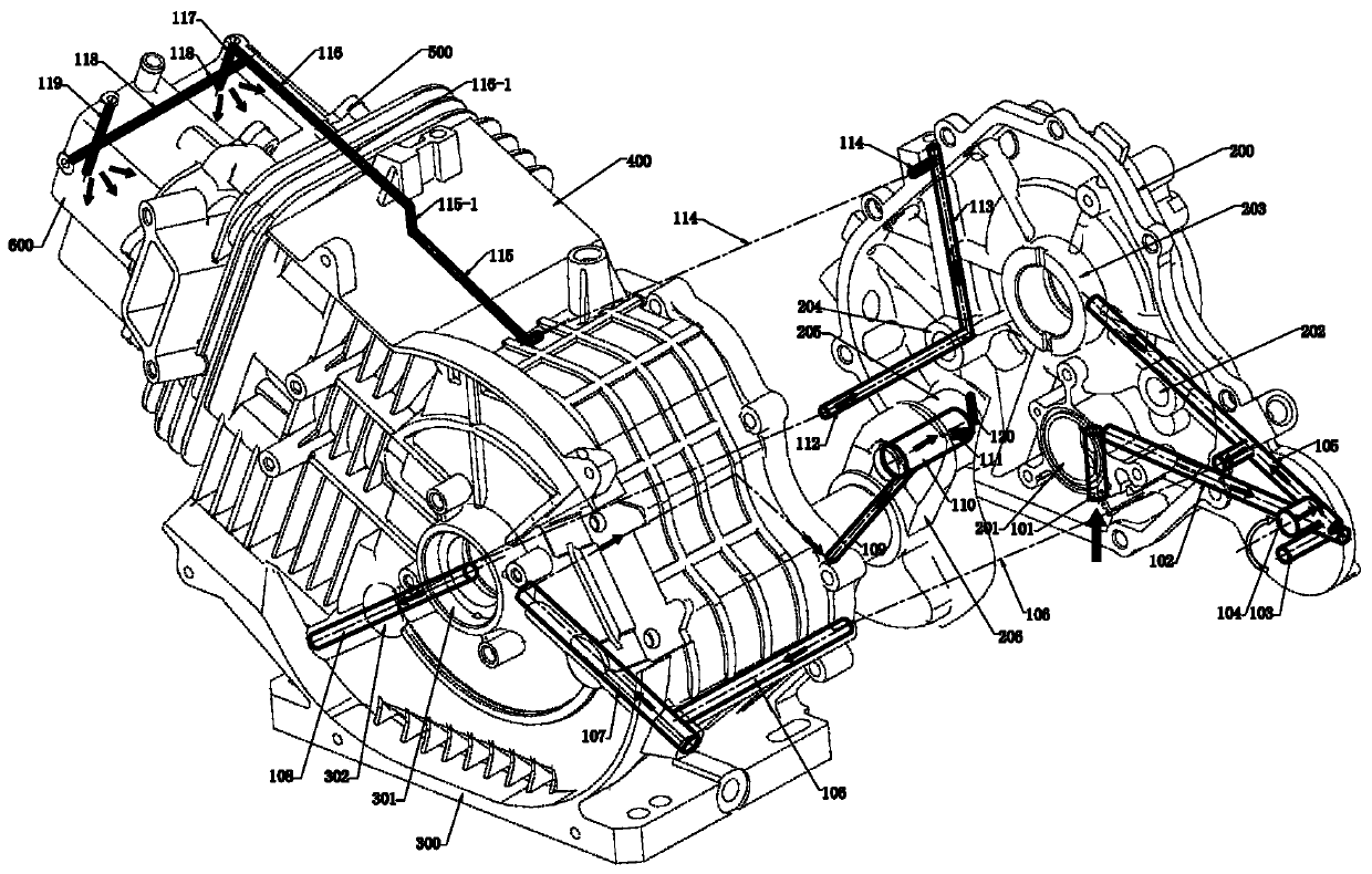
[0031] like figure 1 As shown, this embodiment provides an engine forced lubrication system, including oil passage 101 to oil passage 20 120, oil pump 708, oil cooler 701, filter 704 and filter base 705, oil passage 101 It is vertically arranged at the bottom of the crankcase cover 200 , and its lower end can penetrate into the lubricating oil at the bottom of the crankcase body 300 . The oil pump 708 is installed on the oil pump 708 mounting hole 201 of the crankcase cover 200 , and its suction port communicates with the other end of the oil passage one 101 . The oil passage 2 102 is arranged on the crankcase cover 200 and is arranged horizontally. One end thereof communicates with the discharge port of the oil pump 708, and the other end directly communicates vertically with the oil passage 3 103, forming a linear oil passage as well.

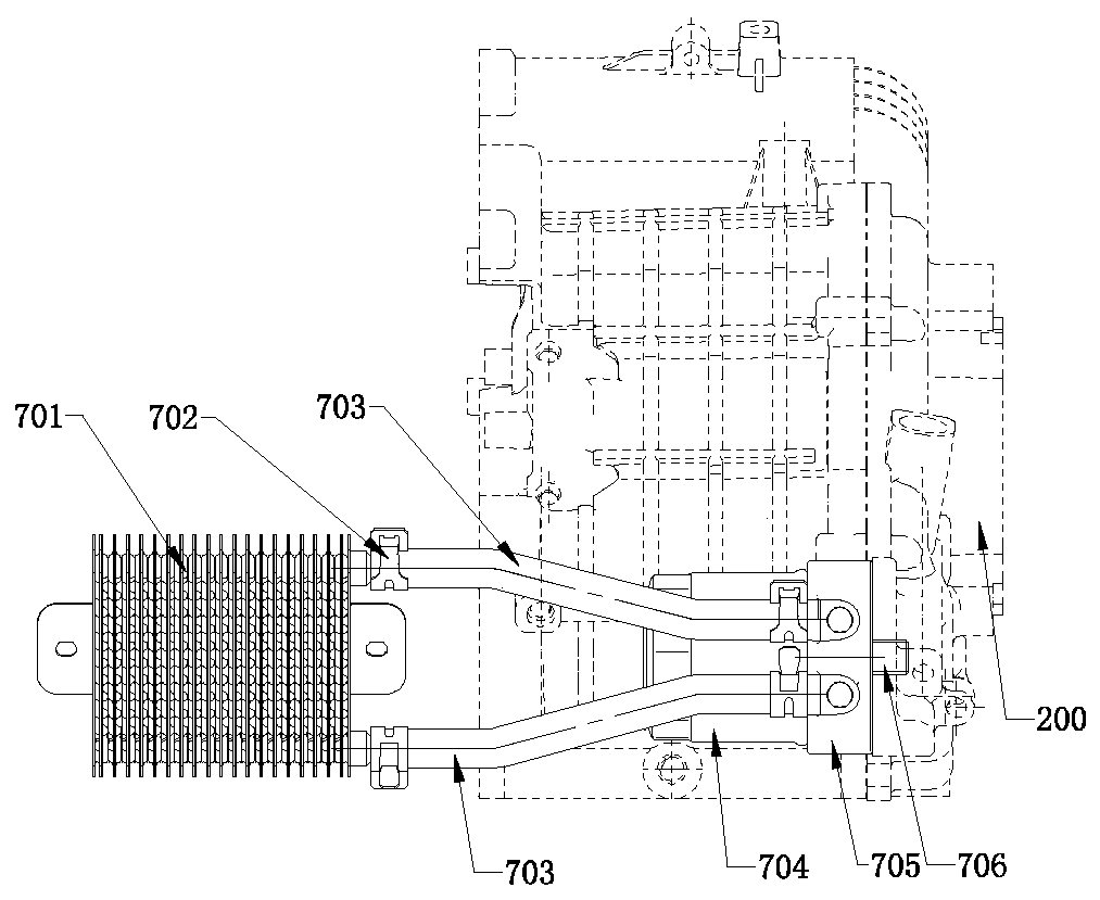
[0032] For the installation and connection of filter base 705 and filter 704, please refer to image 3 , Figure 4 , Figure 5 shown. F...

Embodiment 2

[0049] The difference between this embodiment and Embodiment 1 is that a connecting rod oil groove d is provided between the oil passage ten 110 and the oil passage eleven 111, and the connecting rod oil groove d is arranged on the inner wall surface of the 5-axis hole at the big end of the connecting rod. It is an arc-shaped shallow groove that fits the shape of the inner wall of the 5-axis hole at the big end of the connecting rod, which can fully lubricate the connecting rod 4 and the connecting rod neck 205, thereby reducing friction and improving service life.

[0050] Based on the above, the present invention provides a forced lubricating oil circuit structure of the engine, which adopts a large number of linear oil channels and redesigns the forced lubricating oil circuit, which can not only fully lubricate the components with lubrication requirements, but also combine the ad hoc The design of the filter base 705 and the design of the crankshaft assembly 206 greatly redu...


PUM


Abstract

The invention discloses a forced lubrication oil way system for an engine. The forced lubrication oil way system for the engine comprises a plurality of straight oil ways. The oil ways start from thebottom of a crankcase cover and flow back into a shaft hole of the crankcase cover for lubrication after filtering and cooling, meanwhile, the oil ways are provided with branches and flow to a shaft hole of a crankcase body, a camshaft of the crankcase body and a crank module for lubrication and cooling; and finally, the oil ways enter into a cylinder head cover through an oil passage externally arranged on the outer wall of a cylinder body, and lubricate and cool all parts in the cylinder head cover through a plurality of oil outlets. The forced lubrication oil way system for the engine can improve the overall lubrication performance of the engine, all moving parts in the engine can be lubricated to the greatest extent, the frictional work of the engine is reduced, the power of the engineis improved, and the service life of the engine is prolonged.

Description

technical field [0001] The invention belongs to the field of engine lubricating oil passage systems, in particular to an engine oil forced lubricating oil passage system. Background technique [0002] The existing oil lubricating oil circuit system generally adopts the oil pump to absorb oil (the oil pump is installed on the tank cover). Lubricate one end of the crankshaft through the balance shaft hole of the case cover to the crankshaft hole of the case cover; and then lead one way to the oil passage of the case body to deliver the lubricating oil to the other end of the crankshaft hole of the case body, and the oil passage on the crankshaft at this end will lubricate The oil is sent to the shaft diameter of the crankshaft connecting rod, and the lubricating oil is introduced between the connecting rod and the connecting rod neck, and the relative rotation motion is used to generate splash lubrication to perform splash lubrication on the camshaft, the inside of the piston ...

Claims


Application Information

Patent Timeline
Patent Type & Authority Applications(China)
IPC IPC(8): F01M1/02F01M1/06F01M1/10F01M5/00F01M9/06F01M9/10F02F7/00
Inventor 沈乡情殷贵良徐钢濮光明平鸿光方天泽
Owner 浙江康思特动力机械有限公司
Why Eureka
Try Eureka