Water level sensor

A water level sensor and an integrated technology, applied in the field of sensors, can solve the problems of unreasonable assembly methods of sensors, affecting assembly efficiency and use effect, etc., to achieve improved assembly efficiency and measurement accuracy, reasonable air intake structure design, and reduced assembly process difficulty Effect

Pending Publication Date: 2019-05-03
芜湖乐佳电器有限公司
View PDF0 Cites 2 Cited by
  • Summary
  • Abstract
  • Description
  • Claims
  • Application Information

AI Technical Summary

Problems solved by technology

[0003] The purpose of the present invention is to solve the problem of unreasonable sensor assembly method in the prior art, which affects the assembly efficiency and use effect, and proposes a water level sensor

Method used


Image

  • Water level sensor
  • Water level sensor
  • Water level sensor

Examples


Embodiment 1

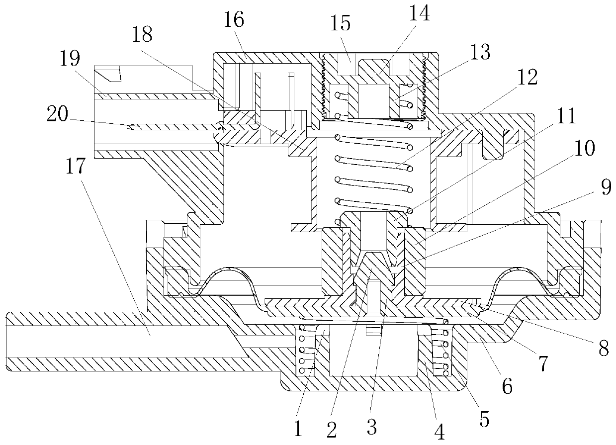
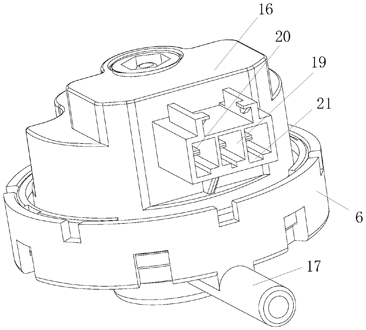
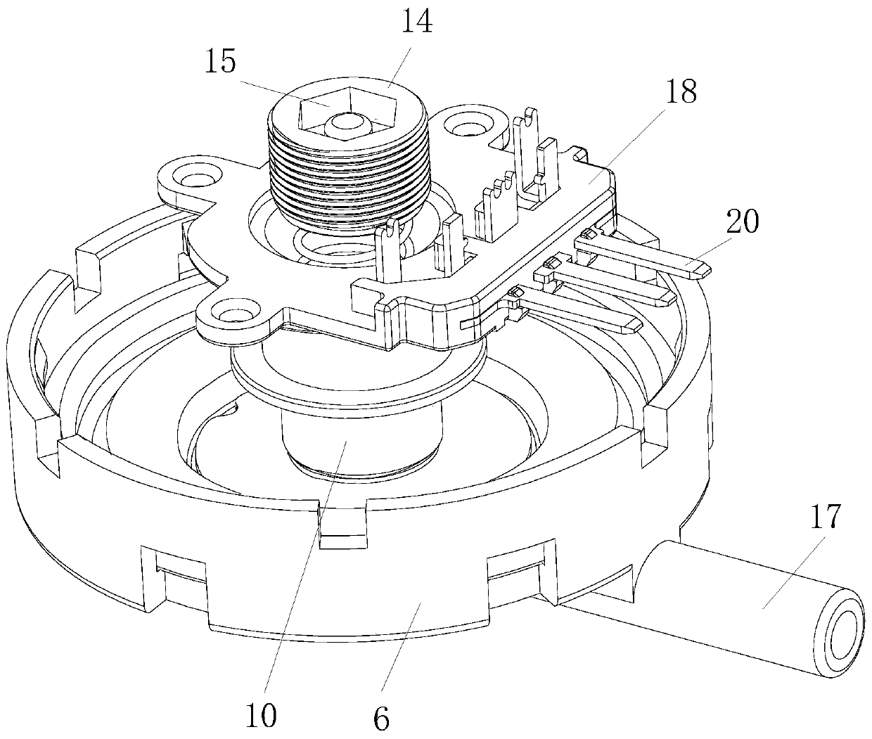
[0023] refer to Figure 1-4 , a water level sensor, comprising a lower casing 6 and an upper casing 16 connected together, one side of the lower casing 6 is provided with an air inlet passage 17, and in a sealed chamber formed between the lower casing 6 and the upper casing 16 There are detection components, the detection components include a silicone diaphragm 7, the silicone diaphragm 7 is fixed between the lower casing 6 and the upper casing 16, a cylinder 4 is arranged in the middle of the lower casing 6, and a coaxial sleeve is arranged on the cylinder 4. The first spring 5, the bottom plane of the silicone diaphragm 7 coincides with the top plane of the first spring 5, the silicone diaphragm 7 is supported on the upper part of the first spring 5, the cylinder 4 and the lower casing 6 are integrally formed, reducing assembly steps, and at the same time The bottom of the diaphragm 7 is provided with a first spring 5 to prevent the silicone diaphragm 7 from being sealed tog...

Embodiment 2

[0028] refer to Figure 1-4 , a water level sensor, comprising a lower casing 6 and an upper casing 16 connected together, one side of the lower casing 6 is provided with an air inlet passage 17, and in a sealed chamber formed between the lower casing 6 and the upper casing 16 There is a detection part, the detection part includes a silicone diaphragm 7, and the silica gel diaphragm 7 is fixed between the lower casing 6 and the upper casing 16, and the sealed chamber is divided into an upper chamber, a lower chamber, and a lower chamber by the silica gel diaphragm 7. The chamber is communicated with the air inlet channel 17, the upper part of the silicone diaphragm 7 is provided with a magnetic core 10, and the upper part of the middle part of the silica gel diaphragm 7 is provided with an integrally formed buckle assembly, which includes a hollow cylindrical section 3, a tapered chuck 2, a cone The outer diameter of the bottom end of the clamp head 2 is greater than the outer d...


PUM


Abstract

The invention relates to the technical field of sensors, more particularly to a water level sensor comprising a lower casing and an upper casing that are connected together. An air inlet channel is formed in one side of the lower casing. A detecting chamber is arranged in a sealed cavity formed between the lower casing and the upper casing and includes a silicone membrane; and the sealed cavity isdivided into an upper chamber and a lower chamber by the silicone membrane. A magnetic core is connected to a buckle assembly through an ejection assembly. The ejector assembly includes a bottom plate and a hollow top rod that are integrated; the magnetic core sleeves the outside of the hollow top rod; and an inductance coil is connected with a wiring terminal arranged at one side of the upper casing. The assembling process difficulty is reduced substantially; the magnetic core can move up and down stably; and the assembly efficiency and measurement accuracy of the sensor are improved substantially. Meanwhile, on the basis of the reasonable structural design of the air inlet at the bottom of the silicone membrane, forces applied on the bottom of the silicone membrane become uniform and fixed-direction uniform-speed movement is realized. The service life of the sensor is prolonged; and the accuracy of the water level detection is improved.

Description

technical field [0001] The invention relates to the technical field of sensors, in particular to a water level sensor. Background technique [0002] The washing machine water level sensor has a simple structure and convenient control, and is widely used in low-end, mid-end, and high-end washing machines. The water level sensor of the washing machine provides a resonant frequency of the LC oscillating circuit to the computer board of the washing machine, and the computer board of the washing machine automatically controls and adjusts the water level of the washing machine according to the resonant frequency signal of the oscillating circuit. The different assembly methods in the sensor manufacturing process will directly affect the use effect of the sensor and affect the assembly efficiency at the same time. Contents of the invention [0003] The purpose of the present invention is to solve the problem of unreasonable sensor assembly method in the prior art, which affects ...

Claims


Application Information

Patent Timeline
Patent Type & Authority Applications(China)
IPC IPC(8): G01F23/26D06F39/08D06F39/00
Inventor 钱勇国
Owner 芜湖乐佳电器有限公司
Why Eureka
Try Eureka