Semi-coaxial optical path receiving laser radar system

A laser radar, laser receiving technology, applied in radio wave measurement system, electromagnetic wave re-radiation, utilization of re-radiation and other directions, to achieve the effect of ensuring authenticity, high resolution, and high measurement accuracy

Active Publication Date: 2019-05-03
XI AN ZHISENSOR TECH CO LTD
View PDF13 Cites 24 Cited by
  • Summary
  • Abstract
  • Description
  • Claims
  • Application Information

AI Technical Summary

Problems solved by technology

[0010] In order to solve the contradiction between echo energy and measurement accuracy, the present invention proposes a semi-coaxial optical path receiving laser radar system

Method used


Image

  • Semi-coaxial optical path receiving laser radar system
  • Semi-coaxial optical path receiving laser radar system
  • Semi-coaxial optical path receiving laser radar system

Examples


Embodiment 1

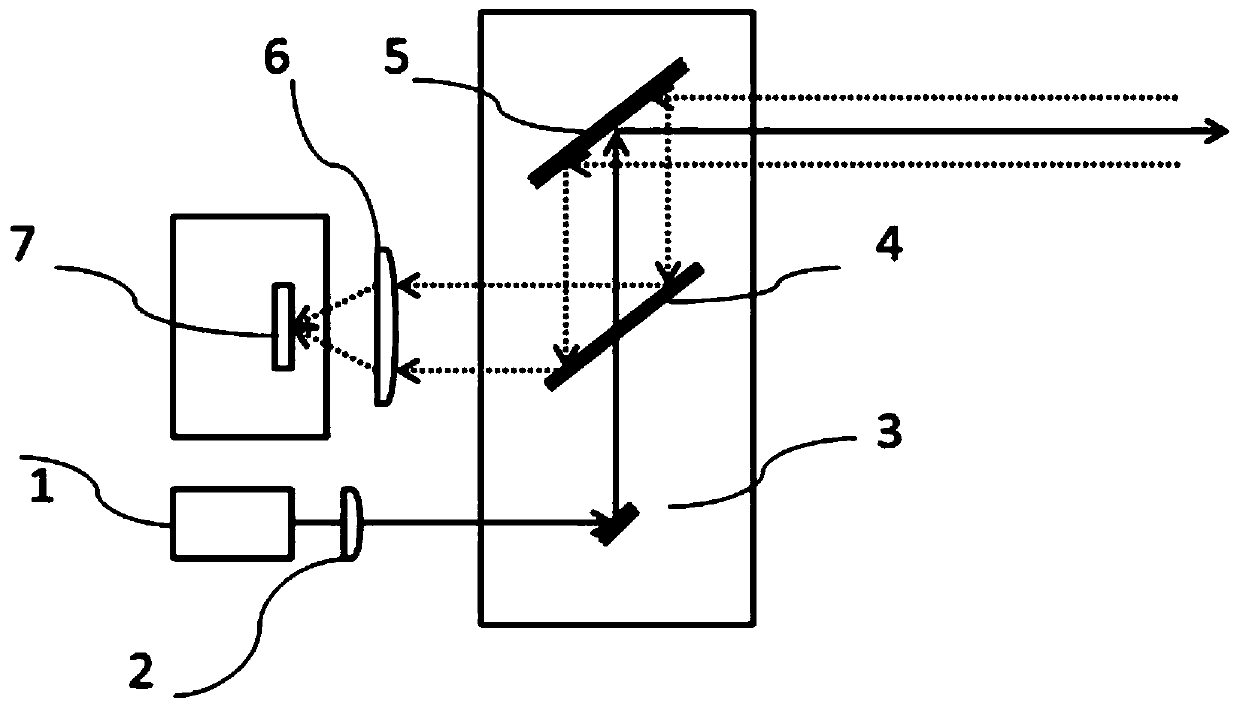
[0039] From figure 1 It can be seen that the semi-coaxial optical path receiving radar galvanometer scanning system in this embodiment includes a pulsed laser 1, a collimator lens 2, a first one-dimensional MEMS galvanometer 3 and a half-mirror 4 arranged sequentially along the optical path, which can Replacing the half-mirror 4 with a polarizing beam splitter, it also includes a second one-dimensional MEMS oscillating mirror 5 arranged in the transmission path of the half-mirror 4 and a receiving lens sequentially arranged in the reflection path of the half-mirror 4 6 and photodetector 7. In this embodiment, the receiving lens 6 is a focusing lens. In other embodiments, in order to realize the scanning requirement of a large field of view, the receiving lens 6 can adopt a wide-angle lens, which is then received by the detector for signal processing. The above-mentioned wide-angle lens is a cylindrical lens, immersed Large field of view receiving lens such as lens or compound...

Embodiment 2

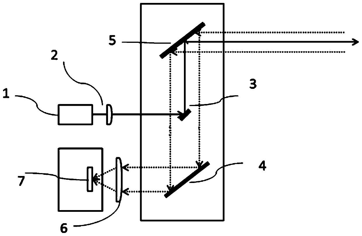
[0044] From figure 2 It can be seen that the semi-coaxial optical path receiving radar galvanometer scanning system in this embodiment includes a pulsed laser 1, a collimating lens 2, a first one-dimensional MEMS galvanometer 3 and a second one-dimensional MEMS galvanometer 5 arranged in sequence along the optical path ; Also includes a total reflection mirror 4 and a receiving lens 6 and a photodetector 7 located in the reflection path of the total reflection mirror 4 in turn. The main function of the collimating mirror 2 is to realize the shaping of the laser spot, to achieve the maximum energy concentration of the pulsed laser, and to improve the emitted light energy and the ability to test farther. The initial position of the first one-dimensional MEMS vibrating mirror 3 is at an angle of 45° to the beam direction, and the initial position of the second one-dimensional MEMS vibrating mirror 5 and the total reflection mirror 4 are parallel to the initial direction of the f...

Embodiment 3

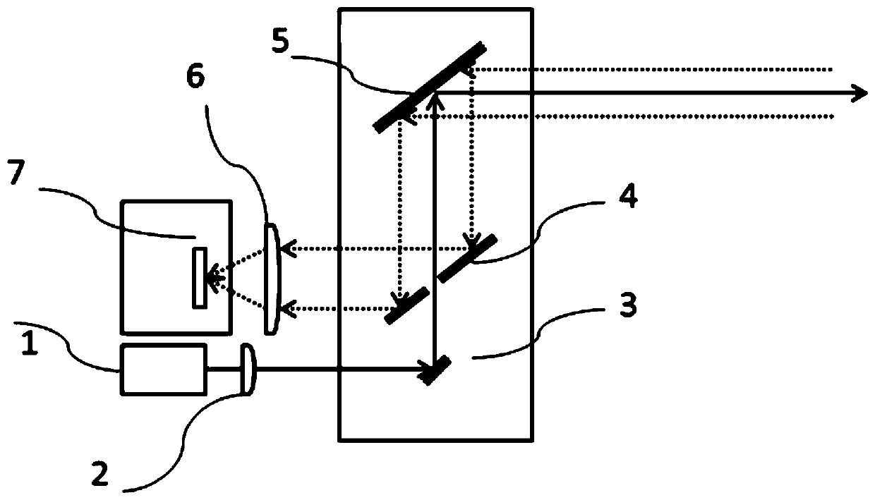
[0048] From image 3 It can be seen that the semi-coaxial optical path receiving radar galvanometer scanning system in this embodiment includes a pulse laser 1, a collimator lens 2, a first one-dimensional MEMS galvanometer 3, and a total reflection mirror with a central opening arranged in sequence along the optical path. 4 and the second one-dimensional MEMS oscillating mirror 5, further comprising a receiving lens 6 and a photodetector 7 sequentially arranged in the reflection optical path of the total reflection mirror 4 with a central opening. The main function of the collimating mirror 2 is to realize the shaping of the laser spot, to achieve the maximum energy concentration of the pulsed laser, and to improve the emitted light energy and the ability to test farther. The first one-dimensional MEMS vibrating mirror 3 is at an angle of 45 degrees to the beam direction at the initial position, the initial position of the second one-dimensional MEMS vibrating mirror 5 and th...


PUM


Abstract

The invention, which belongs to the field of the laser radar optical design system, provides a semi-coaxial optical path receiving laser radar system comprising a laser emitting module, a galvanometerscanning module and a laser receiving module. The galvanometer scanning module includes a first one-dimensional MEMS galvanometer, a second two-dimensional MEMS galvanometer and a reflective opticalelement; the scanning direction of the first one-dimensional MEMS galvanometer is perpendicular to the scanning direction of the second one-dimensional MEMS galvanometer; and the scanning mirror areaof the first one-dimensional MEMS galvanometer is smaller than that of the second one-dimensional MEMS galvanometer. The laser emitting module emits shaped pulsed laser; and the emitted laser passes through the first one-dimensional MEMS galvanometer and the second one-dimensional MEMS galvanometer to realize two-dimensional area array scanning; and a scattered echo signal is reflected by the second one-dimensional MEMS galvanometer and the reflective optical element and then returns to the laser receiving module. Therefore, a conflict problem between the echo energy and measurement accuracy is solved; the high resolution is realized in the process of testing people or objects ahead; and the authenticity of test results is guaranteed to the greatest extent.

Description

technical field [0001] The invention belongs to the field of laser radar optical design systems, and relates to a semi-coaxial optical path receiving laser radar system that improves the accuracy of horizontal measurement. Background technique [0002] Lidar realizes its ranging function by calculating the time difference between the emitted laser light and the receiving time of the echo scattered light. To achieve two-dimensional and three-dimensional scanning, to achieve lidar ranging or three-dimensional imaging, there are many ways to implement lidar: [0003] 1. Traditional mechanical rotary scanning: The laser radar is driven by machinery to produce 360° rotation. The problem is that the external dimension is large, and it will be severely worn after a long time. [0004] 2. All-solid-state scanning (such as optical phased array): the emission angle is changed by adjusting the phase difference of each emission unit in the emission array. The problem is that the cost o...

Claims


Application Information

Patent Timeline
Patent Type & Authority Applications(China)
IPC IPC(8): G01S17/10G01S7/481
Inventor 范乔丹何耀军徐法虎夏长锋乔大勇
Owner XI AN ZHISENSOR TECH CO LTD
Why Eureka
Try Eureka