
Battery production method and battery production device

A manufacturing method and battery technology, applied in secondary battery manufacturing, manufacturing tools, auxiliary devices, etc., can solve problems such as collector foil and wire bonding

Inactive Publication Date: 2019-05-03
JET
View PDF8 Cites 0 Cited by
  • Summary
  • Abstract
  • Description
  • Claims
  • Application Information

AI Technical Summary

Problems solved by technology

However, if the number of current collector foils increases, it is difficult to stably join the current collector foils and lead wires by ultrasonic welding

Method used


Image

  • Battery production method and battery production device
  • Battery production method and battery production device
  • Battery production method and battery production device

Examples


Embodiment Construction

[0025] Embodiments of the present invention will be described in detail below with reference to the accompanying drawings.

[0026] 1. Overall structure

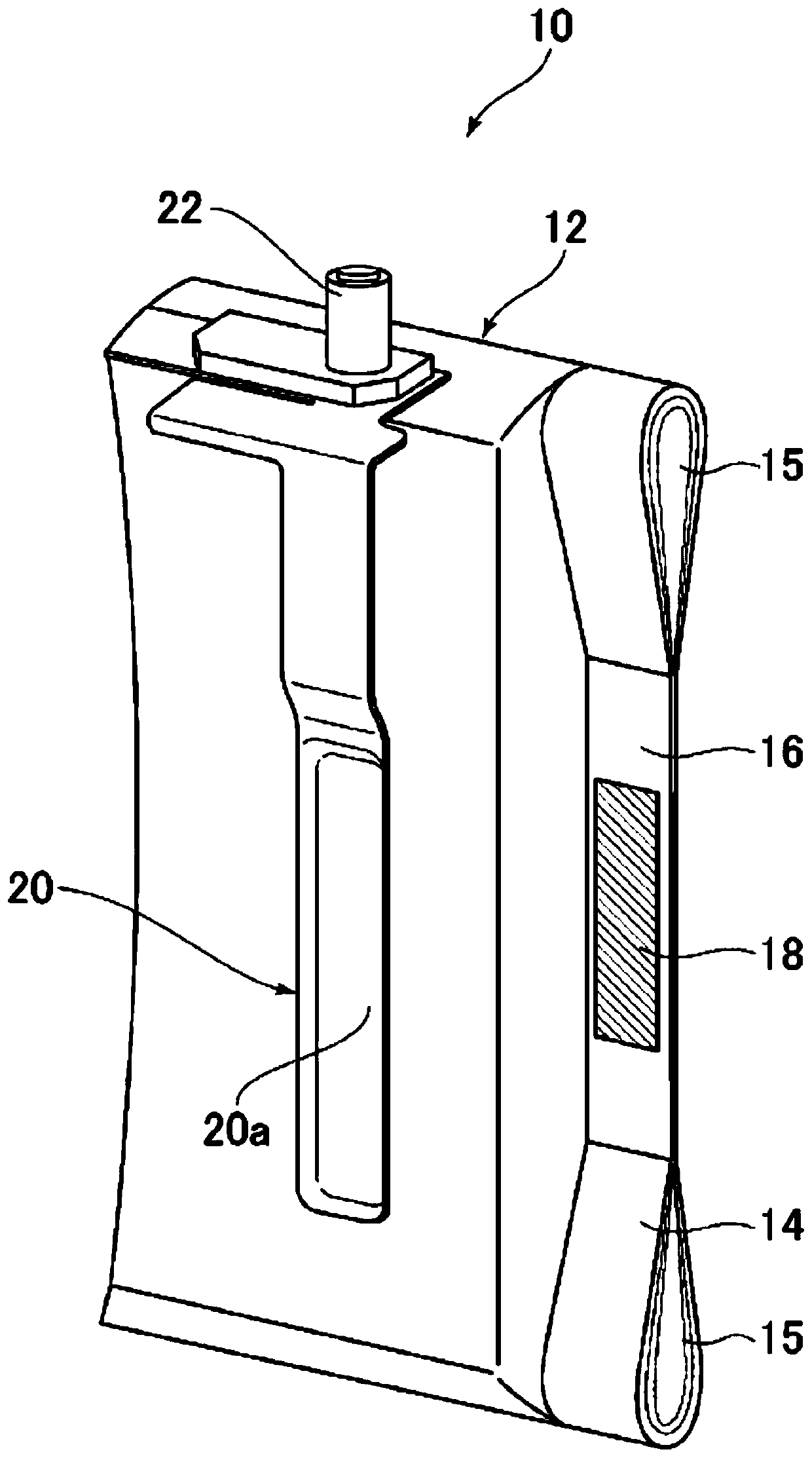
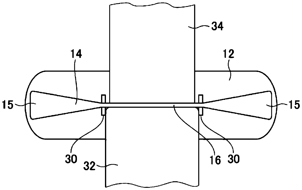
[0027] The battery manufacturing device of the present invention includes a pressurizing unit, a bonding unit, and a judging unit. The pressurizing unit pressurizes predetermined regions of the plurality of collector foils exposed at ends of the electrodes and overlapping each other to form a compressed region in which an interval between adjacent collector foils is reduced.

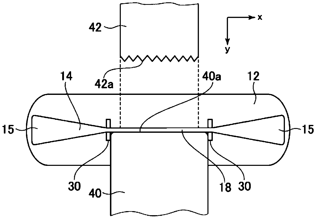
[0028] The joining unit joins a region inside the compressed region of the plurality of current collector foils by ultrasonic welding using a horn and an anvil to form a joint region in which the plurality of current collector foils are integrated. The judging unit judges whether the bonded area is good or not based on an output waveform representing a temporal change in an output value of the horn. Using the battery manufacturing device of the prese...


PUM


Abstract

The present invention provides a battery production method and a battery production device capable of decreasing the occurrence of defects, the method being characterized by: a first step of compressing predetermined regions from a plurality of collector foils (14) superposed onto each other and exposed at an end of an electrode (12), thereby forming a compressed region (16) wherein the interval between adjacent collector foils (14) has been reduced; and a second step of joining by ultrasound welding the regions of the plurality of collector foils (14) inside the compressed region (16), thereby forming a joined region (18) wherein the plurality of collector foils (14) have been turned into a single body.

Description

technical field [0001] The invention relates to a battery manufacturing method and a battery manufacturing device. Background technique [0002] Secondary batteries such as lithium-ion batteries (LIB: Lithium-ion Battery) and nickel metal hydride batteries (nickel metal hydride batteries) are used as power sources for vehicles and as stationary storage batteries, and their capacities are increasing. A secondary battery includes: an electrode exposing a plurality of current collector foils overlapping each other at an end; and a lead connected to the plurality of current collector foils. Usually, an aluminum lead is joined to an aluminum current collector foil in the positive electrode, and a nickel or copper lead is connected to a copper current collector foil in the negative electrode. [0003] Since a large current flows instantaneously in a secondary battery, a plurality of current collector foils and leads are usually joined by integral welding using ultrasonic waves (f...

Claims


Application Information

Patent Timeline
Patent Type & Authority Applications(China)
IPC IPC(8): H01M2/26B23K20/10B23K31/00H01M10/04H01M50/536
CPCB23K31/00B23K20/10Y02E60/10Y02P70/50H01M50/536B23K2101/38B23K37/0461H01M50/531H01M4/64
Inventor 山下雅俊太田垣学桥本茂树吉尾英明
Owner JET
Learn More