
Spiral hole forming drilling tool and piling construction method

A helical and hole-forming technology, which is applied in the direction of drill pipe, drill pipe, sheet pile wall, etc., can solve the problems of weak horizontal shear resistance, affecting pile bearing capacity, and strong compaction of soil, and achieves good compaction effect , Eliminate adverse effects, strong effect of squeezing soil

Pending Publication Date: 2019-05-07
刘守进
View PDF0 Cites 0 Cited by
  • Summary
  • Abstract
  • Description
  • Claims
  • Application Information

AI Technical Summary

Problems solved by technology

Long auger bored grouting piles are completely soil-discharging piles, and the construction will produce a large amount of residual soil. There is empty soil at the bottom of the piles, which affects the bearing capacity of the piles; screw piles are partial soil-discharging piles, which are It is completely non-draining process, and the negative effect of soil compaction is large, especially the rock and soil layer with low compressibility cannot be drilled through, and the piles formed are piles with different diameters. The hole pressure filling pile has been improved, and the amount of residual soil discharge is much less than that; the SDS pile is a non-discharge pile, and the process of forming the pile hole is to first turn the rock and soil in the cylindrical pile hole into a loose and free shape by rotary cutting. The loose rock and soil are squeezed towards the wall of the pile hole during the uploading process along the spiral blades. The path of the whole uploading process is very short, and the compacted soil is highly concentrated. It is difficult to penetrate the rock and soil layer with low compressibility. There is virtual soil at the bottom, which affects the bearing capacity of the pile

Method used


Image

  • Spiral hole forming drilling tool and piling construction method
  • Spiral hole forming drilling tool and piling construction method
  • Spiral hole forming drilling tool and piling construction method

Examples


Embodiment 1

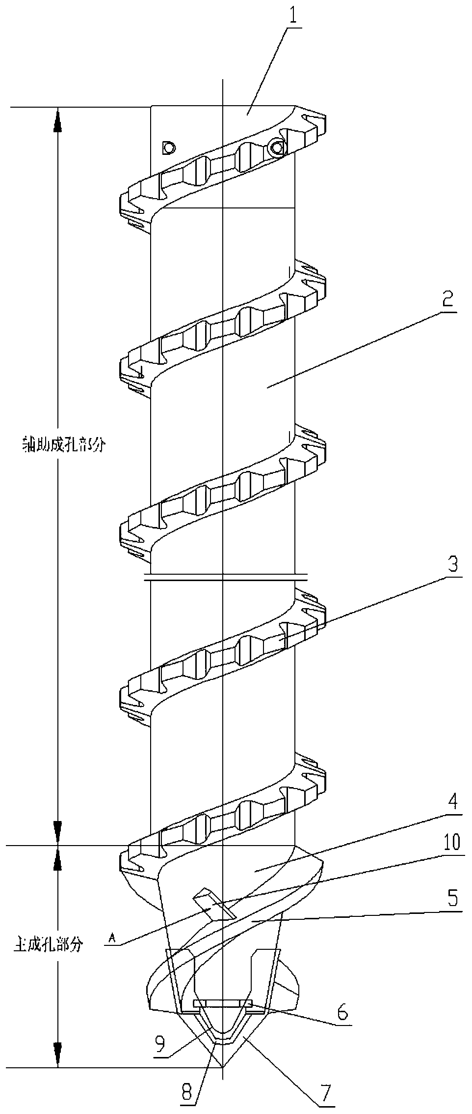
[0043] Such as Figure 1-Figure 4 , This embodiment provides a helical hole-forming drilling tool in which the core pipe of the main hole-forming part is a truncated cone and a soil retaining block is provided.

[0044] (1) A helical hole-forming drilling tool is composed of an auxiliary hole-forming part and a main hole-forming part.

[0045] The auxiliary hole-forming part is composed of several joints 1, several outer pipes 2 and spiral extruding blades I3. After several outer pipes 2 are connected together through the joint 1, the spiral extruding blade I3 is wound on the joint 1 and the outer pipe 2, and the shape formed by the outer edge of the spiral extruding blade I3 is cylindrical. The joint 1 installed at the upper end of the topmost outer pipe 2 is used to connect the spiral hole drilling tool with the power head of the pile driver. The lower end of the outer tube 2 at the bottom is fixed with the core tube 4 of the main hole-forming part. The joint 1 can be a f...

Embodiment 2

[0063] Such as Figure 5-Figure 6 , This embodiment provides a spiral hole-forming drilling tool in which the core pipe of the main hole-forming part is cylindrical and has soil retaining and squeezing blocks. The helical hole-forming drilling tool provided in this embodiment is composed of an auxiliary hole-forming part and a main hole-forming part.

[0064] The auxiliary hole-forming part is composed of several joints 1, several outer pipes 2 and spiral extruding blades I3.

[0065] The main hole forming part is composed of the core pipe 4, the spiral extruding soil blade II 5 and the drill door device.

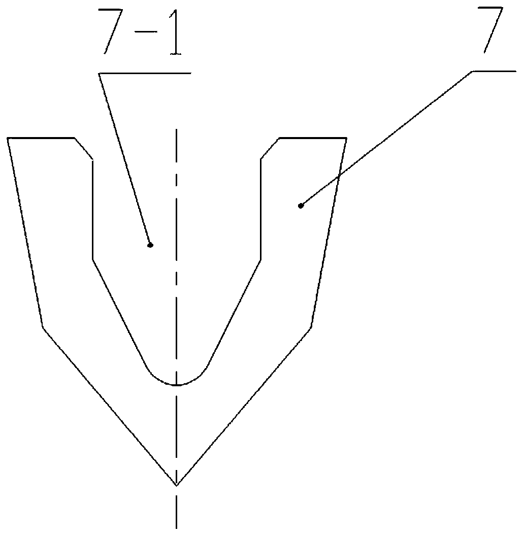
[0066] The drill door device includes a hinge group 6, a drill tip 7, a U-shaped coaming plate 8 and a drill door 9.

[0067] Several soil retaining blocks 10 are provided.

[0068] The structures of the auxiliary hole-forming part, the main hole-forming part and the soil retaining and squeezing block 10 are the same as those in Embodiment 1, except that the core pipe 4 ...

Embodiment 3

[0071] Such as Figure 7-Figure 8 , This embodiment provides a spiral hole-forming drilling tool in which the core pipe of the main hole-forming part is a truncated cone without soil retaining and squeezing blocks.

[0072] (1) A helical hole-forming drilling tool is composed of an auxiliary hole-forming part and a main hole-forming part.

[0073] The auxiliary hole-forming part is composed of several joints 1, several outer pipes 2 and spiral extruding blades I3. After several outer pipes 2 are connected together through the joint 1, the spiral extruding blade I3 is wound on the joint 1 and the outer pipe 2, and the shape formed by the outer edge of the spiral extruding blade I3 is cylindrical. The joint 1 installed at the upper end of the topmost outer pipe 2 is used to connect the spiral hole drilling tool with the power head of the pile driver. The lower end of the outer tube 2 at the bottom is fixed with the core tube 4 of the main hole-forming part. The joint 1 can be...


PUM


Abstract

The invention relates to a spiral hole forming drilling tool and a piling construction method. The spiral hole forming drilling tool comprises an auxiliary hole forming part and a main hole forming part; in the main hole forming part, the upper end of a core pipe is fixed to an outer pipe, a drill bit door device is arranged at the lower end of the core pipe, a spiral soil squeezing blade II is wound outside the core pipe and provided with a plurality of soil retaining and soil squeezing blocks, and the soil retaining and soil squeezing blocks are arranged on the spiral soil squeezing blade IIand are fixed through the core pipe and the spiral soil squeezing blade II. The drilling tool is used for hole forming; in the hole forming process, most of rock soil is directly squeezed in the aperture downward direction by a drill tip and the spiral soil squeezing blade II of the main hole forming part, and a small part of the rock soil is conveyed along the upper curved surface of the spiralsoil squeezing blade II from bottom to top; in the conveying process, the soil retaining and soil squeezing blocks squeeze the rock soil to the aperture downward direction again, so that a tiny part of rock soil is conveyed to the auxiliary hole forming part. The drilling tool is wide in applicable geological condition, high in pile bearing capability, capable of saving energy, efficient and environmentally friendly.

Description

technical field [0001] The invention relates to the field of building pile foundation construction, in particular to a spiral hole-forming drilling tool and a construction method for building piles. Background technique [0002] In the existing construction pile foundations, cast-in-place piles account for a large proportion, especially the use of pump-poured concrete, which has the advantages of good adhesion between the pile and the soil around the pile, is not affected by groundwater, and has high construction efficiency. It is more favored by developers. Commonly used pile types include long auger bored grouting piles, screw piles, SDS piles, etc. Long auger bored grouting piles are completely soil-discharging piles, and the construction will produce a large amount of residual soil. There is empty soil at the bottom of the piles, which affects the bearing capacity of the piles; screw piles are partial soil-discharging piles, which are It is completely non-draining proc...

Claims


Application Information

Patent Timeline
Patent Type & Authority Applications(China)
IPC IPC(8): E21B17/22E02D5/36
Inventor 刘守进李殊睿刘帅夏日光
Owner 刘守进
Learn More