A method for suppressing combustion pressure pulsation by using high-frequency excitation discharge side plasma

A technology of plasma and pressure pulsation, applied in the direction of plasma, combustion method, combustion chamber, etc., can solve the problems of mechanical loss, large delay in actuation time, insufficient actuation frequency, etc.

Active Publication Date: 2021-04-23
HARBIN INST OF TECH
View PDF7 Cites 0 Cited by
  • Summary
  • Abstract
  • Description
  • Claims
  • Application Information

AI Technical Summary

Problems solved by technology

[0006] The present invention aims to solve the technical problems of insufficient actuation frequency, large actuation time delay and mechanical loss in the existing method for suppressing combustion pressure pulsation, and provides a method for suppressing combustion pressure pulsation by high-frequency exciting discharge side plasma

Method used


Image

  • A method for suppressing combustion pressure pulsation by using high-frequency excitation discharge side plasma
  • A method for suppressing combustion pressure pulsation by using high-frequency excitation discharge side plasma
  • A method for suppressing combustion pressure pulsation by using high-frequency excitation discharge side plasma

Examples


specific Embodiment approach 1

[0014] Embodiment 1: This embodiment is a method for high-frequency excitation discharge side plasma to suppress combustion pressure pulsation, which is specifically carried out according to the following steps:

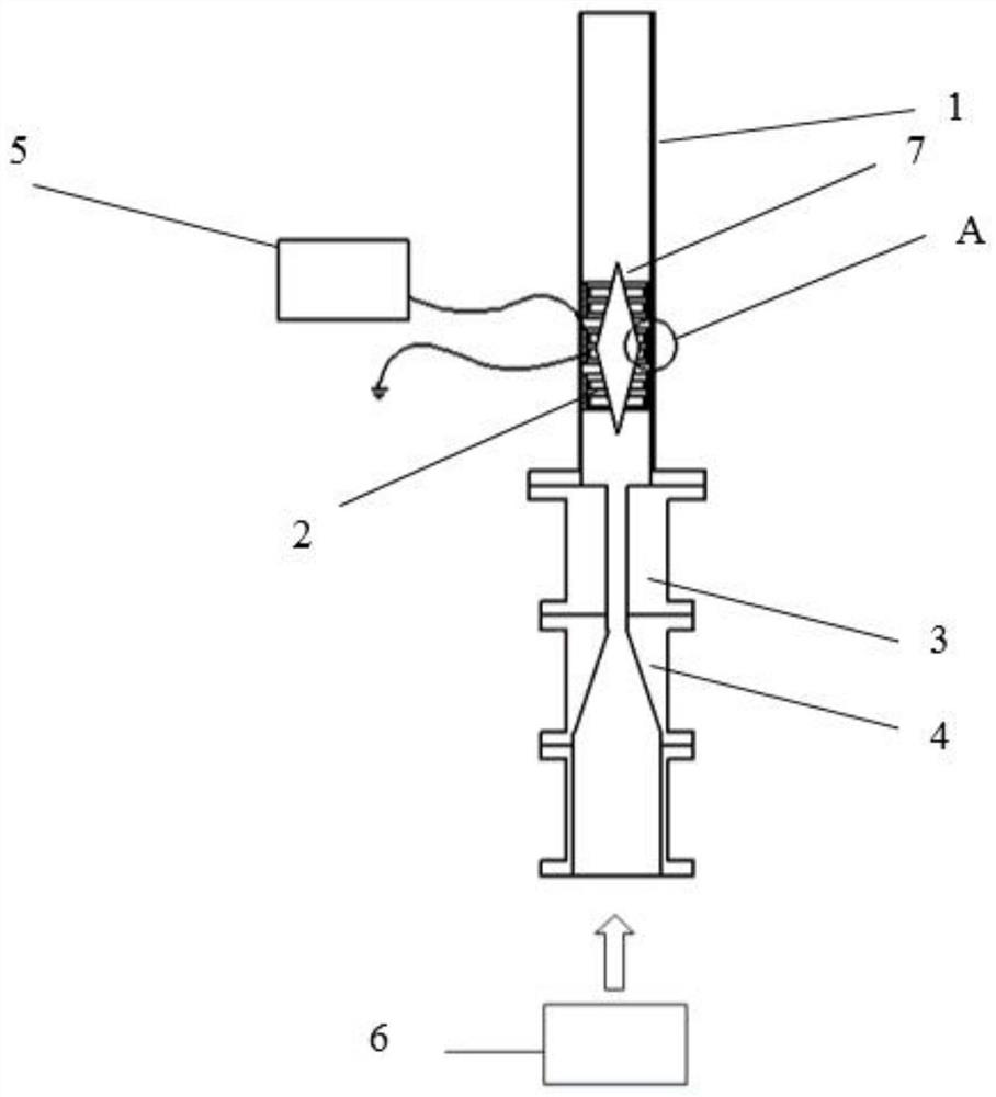
[0015] The annular DBD electrode is placed around the side wall of the combustion chamber, and the height is located around the flame. The annular DBD electrode is connected to the output end of the power supply outside the combustion chamber, and the combustible premixed gas is introduced into the combustion chamber and ignited. When thermoacoustic oscillation occurs in the combustion chamber and accompanied by a certain degree of pressure pulsation, the power supply outside the combustion chamber is activated, so that the annular DBD electrode generates plasma discharge inside the combustion chamber, and acts on the side of the thermoacoustic oscillation flame inside the combustion chamber , the discharge frequency of the plasma is adjusted to be an integer multiple...

specific Embodiment approach 2

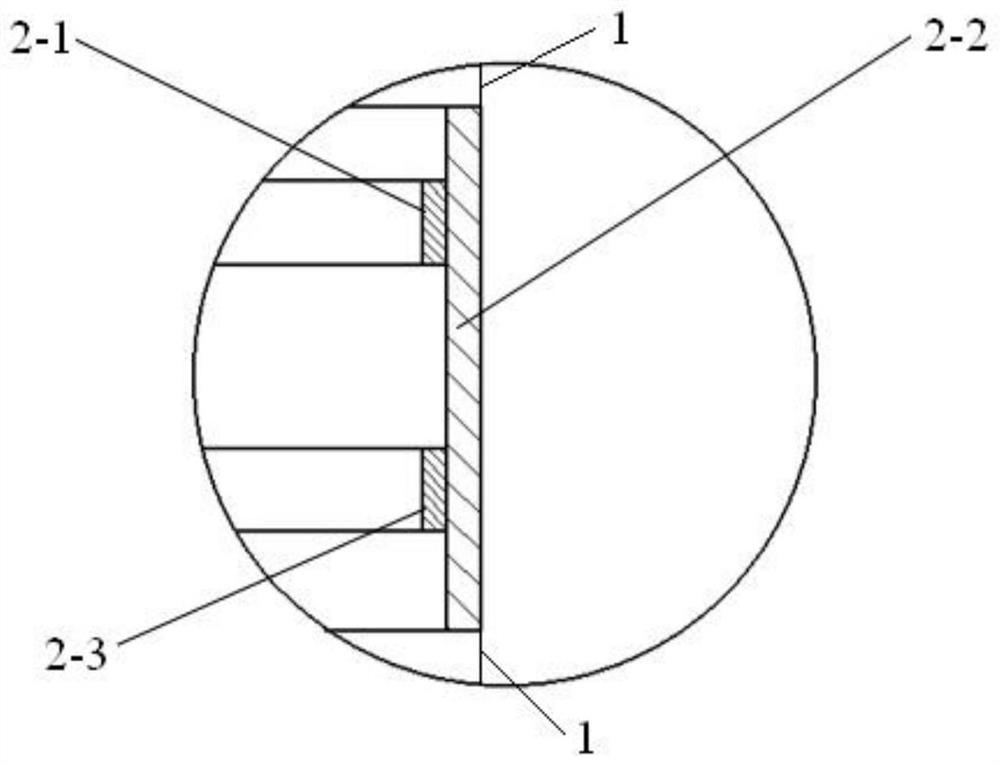
[0016] Embodiment 2: The difference between this embodiment and Embodiment 1 is that the annular DBD electrode is composed of a high-voltage electrode terminal, an insulating medium and a ground electrode terminal; the high-voltage electrode terminal and the output of the power supply outside the combustion chamber The terminal is connected to the ground, the ground electrode terminal is grounded, the insulating medium is annularly attached to the inner wall of the combustion chamber, the high-voltage electrode end is annularly attached to the inner wall of the insulating medium, and the ground electrode end is annularly attached to the inner wall of the insulating medium. The terminal is parallel to the ground electrode terminal and the high voltage electrode terminal is located above the ground electrode terminal. Others are the same as the first embodiment.

specific Embodiment approach 3

[0017] Embodiment 3: The difference between this embodiment and Embodiment 1 or 2 is that the power supply is a pulse power supply, the voltage is 0-10 kV, and the maximum pulse repetition frequency can reach 3 kHz. Others are the same as in the first or second embodiment.


PUM


Abstract

A method for suppressing combustion pressure pulsation by high-frequency excitation discharge side plasma relates to a method for suppressing pressure pulsation in thermoacoustic oscillation phenomenon. The present invention uses side plasma as a dynamic and active way to regulate the pressure pulsation state that occurs during the combustion process of the combustion chamber under certain working conditions. This invention uses dielectric barrier (DBD) discharge to generate plasma on the flame side of the combustion chamber. By adjusting the flame concentration area and changing the distance of the flame main heat release area relative to the combustion chamber outlet, the pressure pulsation in the combustion chamber is reflected from the combustion chamber outlet. The length of the return path changes, and the phase difference between the pressure pulsation and the flame heat release rate changes, which destroys the original conditions for thermoacoustic oscillation, thereby reducing or even disappearing the pressure pulsation in the combustion chamber.

Description

Technical field [0001] The present invention relates to a method for suppressing combustion pressure pulsation. Background technique [0002] Under certain operating conditions, some unexpected unstable conditions will occur inside the combustion chamber, that is, when the relative phase between sound pressure and unsteady heat release is between +90° and -90°, the combustion system's Energy will be amplified. If this amplified energy is greater than the energy dissipated at the combustion chamber boundary, the average net energy accumulated in one oscillation cycle of the combustion chamber will increase, ultimately leading to the occurrence of thermoacoustic oscillation phenomena. On the one hand, this unstable phenomenon can promote fuel-air mixing, enhance the mixing effect, and facilitate combustion; but on the other hand, it can lead to additional pressure, high-amplitude oscillations of the flow field and flame, and thermal load. As the temperature increases, the pr...

Claims


Application Information

Patent Timeline
Patent Type & Authority Patents(China)
IPC IPC(8): F23R3/00H05H1/24
Inventor 唐井峰杨广薇郭宸于达仁
Owner HARBIN INST OF TECH
Why Eureka
Try Eureka