
Active solar heat-gathering and energy-storage system and method thereof

A technology of solar heat concentrating and energy storage system, applied in the field of photovoltaic photothermal, which can solve the problems of low photoelectric efficiency, difficulty in upgrading, and small energy efficiency ratio of photovoltaic products, and achieve the effect of maintaining the working temperature range and improving the utilization rate

Pending Publication Date: 2019-05-07
青岛智睿昌晟新能源科技有限公司
View PDF0 Cites 4 Cited by
  • Summary
  • Abstract
  • Description
  • Claims
  • Application Information

AI Technical Summary

Problems solved by technology

During the period from 2012 to 2017, the cost of my country's traditional solar photovoltaic industry chain has been reduced by nearly half, and the gross profit of each link in the photovoltaic industry chain has also been fundamentally differentiated. The energy efficiency ratio of photovoltaic products has been compressed smaller and smaller. It is difficult to have a substantial improvement
[0005] 3. In the actual use process, the existing photovoltaic panels are prone to frost and even freezing in the outdoor environment in winter. Under the premise that the heat in the air is reduced and the light energy is not enough to defrost and freeze, the efficiency of converting solar energy into photovoltaics is greatly improved. reduce
However, there is no effective means of defrosting and defrosting, and defrosting is usually done manually or by electric heating, which is time-consuming and labor-intensive, and wastes a lot of energy.

Method used


Image

  • Active solar heat-gathering and energy-storage system and method thereof
  • Active solar heat-gathering and energy-storage system and method thereof
  • Active solar heat-gathering and energy-storage system and method thereof

Examples


Embodiment 1

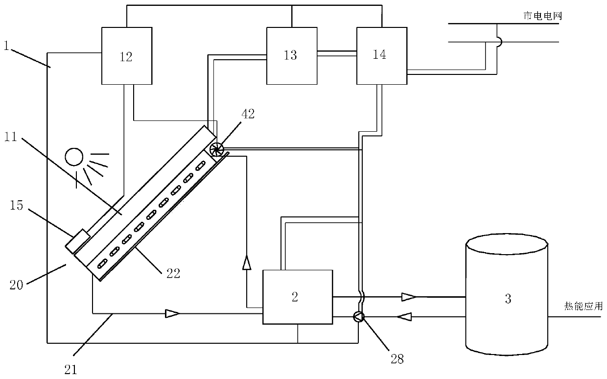
[0046] Example 1, such as Figure 1 to Figure 6 As shown, the active solar thermal energy storage system mainly has the following devices connected to each other in sequence:

[0047] The photovoltaic power generation device 1 converts visible light into photoelectricity by absorbing visible light through the photovoltaic panel 11;

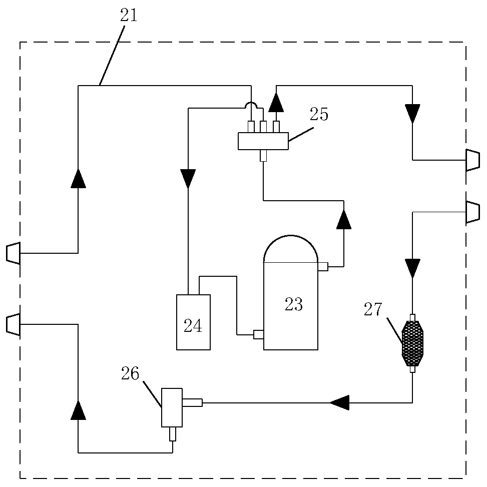
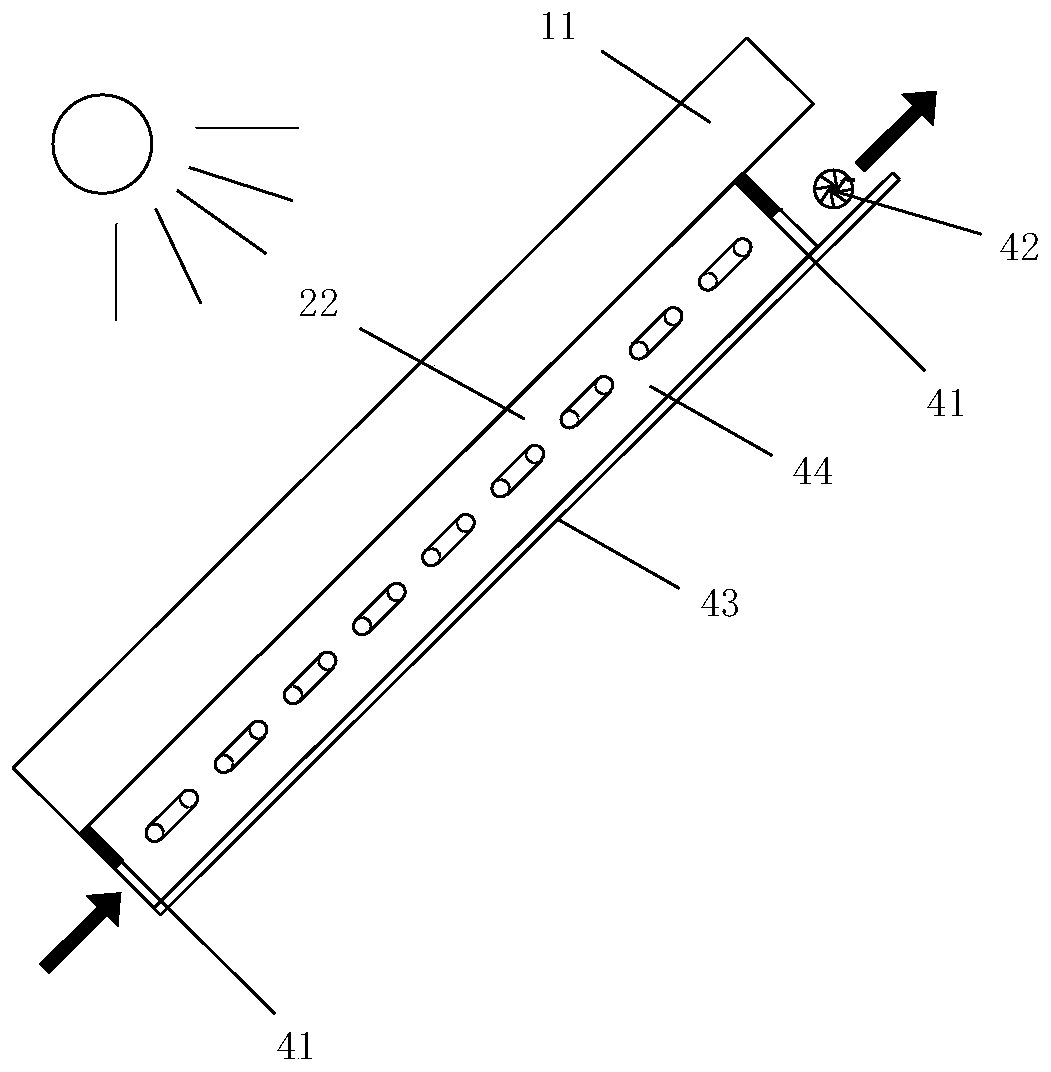
[0048] The heat pump device 2 is used to transfer the heat energy generated by the photovoltaic panel 11 to the energy storage device 3 through the refrigerant circulation pipeline 21; the evaporator assembly 22 of the heat pump device 2 is connected to the photovoltaic panel 11 to form a heat collecting device 20;

[0049] The energy storage device 3 is used to absorb and store the heat transported in one direction from the heat pump device 2 .

[0050] The photovoltaic power generation device 1 also includes a controller 12 , a storage battery 13 , an inverter 14 and a sensor 15 .

[0051] Among them, such as figure 1 As shown, the controller...

Embodiment 2

[0077] Example 2, such as Figure 7 and Figure 8 As shown, in the active solar thermal energy storage system, the evaporator assembly 22 is preferably a one-way multi-channel heat exchanger 50 .

[0078] The one-way multi-channel heat exchanger 50 has multiple groups of parallel heat exchange tubes 53 connected in parallel between the inlet header 51 and the outlet header 52;

[0079] The heat exchange tube 53 is tightly connected to the bottom plate 54, and the bottom plate 54 is closely attached to the photovoltaic panel 11 through the heat-conducting adhesive 29;

[0080] The heat exchange tube 53 has a cross-sectional structure of a flat tube and / or a D-shaped tube to increase the contact heat exchange area;

[0081] The refrigerant fluid flows in from the inlet header 51 in the upper area, divides the flow evenly in the heat exchange tubes 53, and finally flows out from the outlet header 52; one side of the heat exchanger has a bottom plate 54, and a plurality of heat ...

Embodiment 3

[0082] Example 3, such as Figure 9 and Figure 10As shown, in the active solar thermal energy storage system, the evaporator assembly 22 is preferably a plate-and-tube heat exchanger 60 .

[0083] A multi-directional, multi-channel tube 62 is formed on the plate 61 through an inflation process, and the refrigerant circulates between the inflow manifold 63 and the outflow manifold 64;

[0084] On the same side of the plate-and-tube heat exchanger 60 , a layer of heat-conducting adhesive 29 is coated on the joints between the plate 61 and the tube 62 and the photovoltaic panel 11 respectively;

[0085] The tube 62 has a flat tube and / or D-shaped tube cross-sectional structure;

[0086] The refrigerant enters from the inflow main pipe 63 and is divided into multiple flow channels, and flows out from the outflow main pipe 64 after several times of back and forth cycles; the contact side of the heat exchanger and the photovoltaic panel 11 transfers heat through heat conduction, ...


PUM


Abstract

The invention discloses an active solar heat-gathering and energy-storage system and a method thereof. The invention discloses a new active heat-gathering and energy-storage system and method on the basis of organic combination for a photovoltaic power generation technology and a heat pump cycle technology. The new active heat-gathering and energy-storage system and method aim at effectively transmitting and storing the heat energy formed by absorbing solar energy, so that the absorption and conversion efficiency for the solar energy is increased as a whole, and the energy efficiency ratio andthe market value of a photovoltaic product are further increased. The system mainly comprises the following devices which are mutually connected in sequence: a photovoltaic power generation device, aheat pump device and an energy accumulation device, wherein the photovoltaic power generation device absorbs visible light through a photovoltaic panel and convers the visible light to light electricity; the heat pump device is used for transferring the heat energy generated by the photovoltaic panel to the energy accumulation device through a refrigerant cycle pipeline; an evaporator assembly ofthe heat pump device is connected with the photovoltaic panel to form a heat-gathering device; and the energy accumulation device is used for absorbing and storing the heat unidirectionally conveyedfrom the heat pump device.

Description

technical field [0001] The invention is based on the organic combination of photovoltaic power generation and heat pump cycle technology, thereby realizing a brand-new active solar thermal energy storage system and its method, belonging to the field of photovoltaic photothermal technology. Background technique [0002] Existing solar photovoltaic power generation equipment has been widely used, and solar energy can be converted into photoelectricity through photovoltaic modules. However, in the field of solar photovoltaic power generation, the photovoltaic systems and control methods currently used have the following problems and defects: [0003] 1. The utilization efficiency of solar energy resources is low and the waste is serious. In the solar spectrum, only part of the photon energy of visible light can be converted into photoelectricity, and other photon energy, as well as infrared energy accounting for about 53%, are released in the form of ordinary heat energy, so t...

Claims


Application Information

Patent Timeline
IPC IPC(8): F24S60/00F24S20/40F24D15/02F24D15/04F24D17/02H02S40/44
CPCY02E10/40Y02E10/50Y02E10/60
Inventor 朱国华杨明卿陶海波张恒敬颜承恩周霞
Owner 青岛智睿昌晟新能源科技有限公司
Learn More