Heat transfer pipe and cracking furnace

A heat transfer tube and cracking furnace technology, applied in the field of heat transfer tubes and cracking furnaces, can solve the problems of high thermal stress, increased pressure drop, large fluid resistance, etc.

Active Publication Date: 2019-05-07
CHINA PETROLEUM & CHEM CORP +1
View PDF8 Cites 6 Cited by
  • Summary
  • Abstract
  • Description
  • Claims
  • Application Information

AI Technical Summary

Problems solved by technology

Although the existing enhanced heat transfer tube can enhance the heat transfer effect, it has a large resistance to the fluid, w

Method used


Image

  • Heat transfer pipe and cracking furnace
  • Heat transfer pipe and cracking furnace
  • Heat transfer pipe and cracking furnace

Examples


Embodiment 1

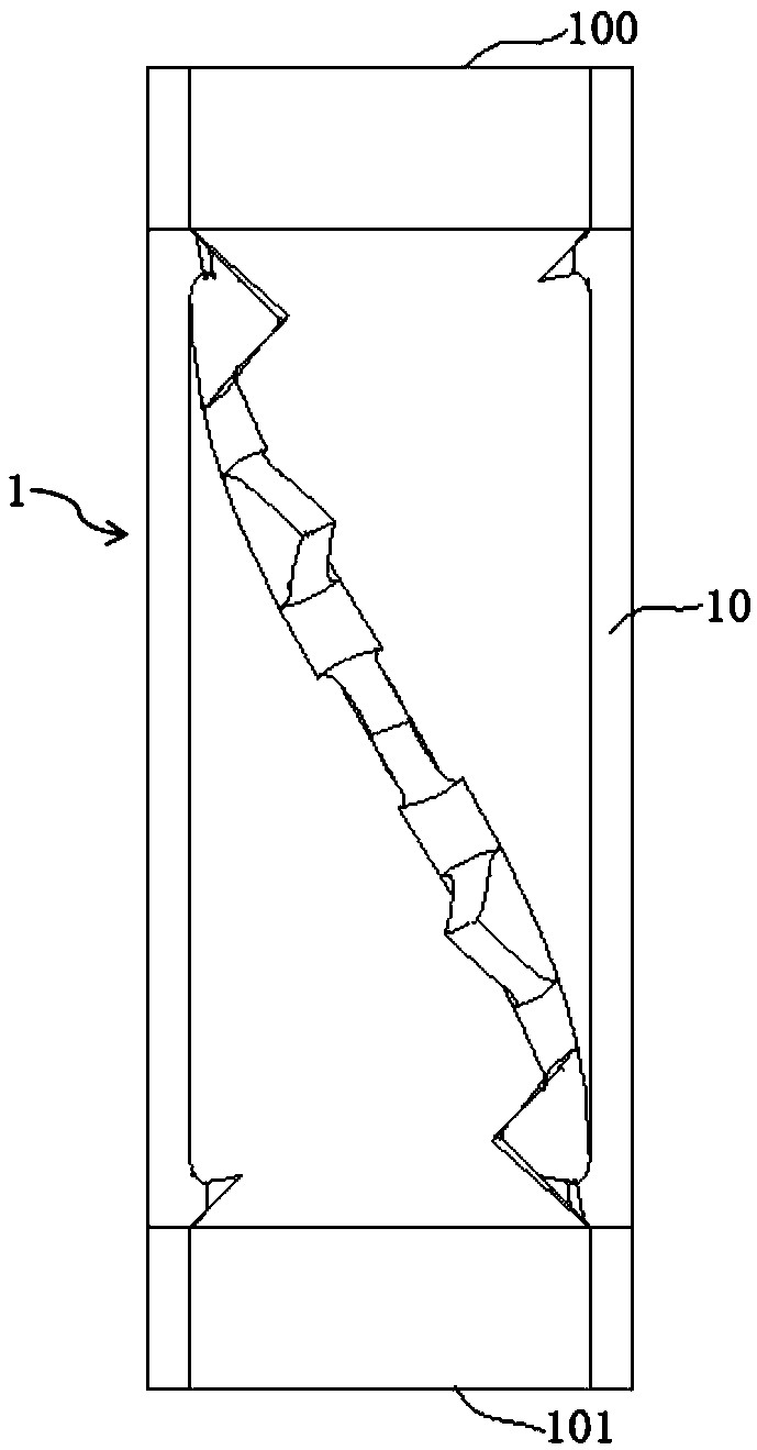
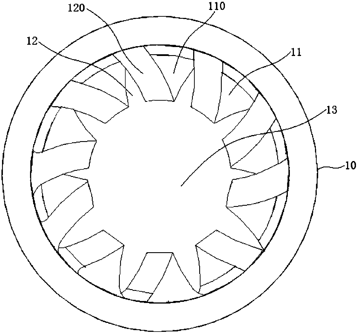
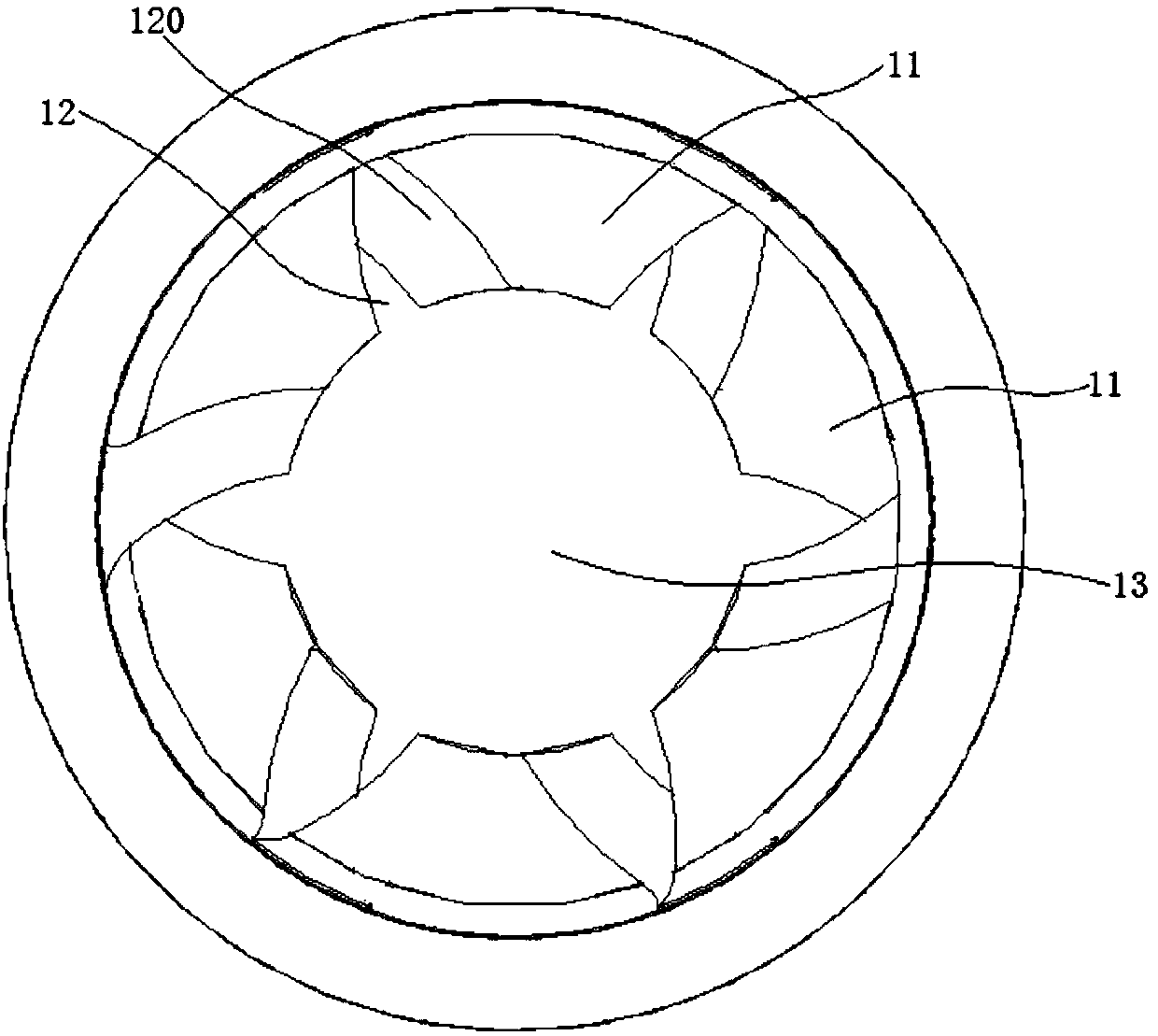
[0038] A plurality of radiant furnace tube assemblies are arranged in the radiant chamber of the cracking furnace, and heat transfer tubes 1 are arranged in three of the radiant furnace tube assemblies, and each radiant furnace tube assembly is provided with Two heat transfer tubes 1 arranged at intervals, the inner diameter of each heat transfer tube 1 is 70mm, in each radiation furnace tube assembly, the axial length of the radiation furnace tube between two adjacent heat transfer tubes 1 is 50 times the inner diameter of the heat transfer tube 1. The structure of each heat transfer tube 1 is: two twisted sheets 11 are arranged on the inner surface of the tube body 10, each twisted sheet 11 includes a plurality of fins 110, and the plurality of fins 110 are along the axial direction of the tube body 10 Extending in a spiral shape, the length of each rib 110 along the direction of spiral extension is 10mm, and each rib 110 is as figure 2 It is roughly triangular in shape, t...


PUM

PropertyMeasurementUnit
Rotation angleaaaaaaaaaa

Abstract

The invention relates to the technical field of fluid heat transfer. The invention discloses a heat transfer pipe and a cracking furnace. The heat transfer pipe (1) comprises a tubular pipe body (10)provided with an inlet (100) allowing fluid to enter and an outlet (101) allowing the fluid to flow out, wherein a twisted sheet (11) is arranged on the inner surface of the pipe body (10), the twisted sheet (11) comprises a plurality of ribs (110) protruding towards the interior of the pipe body (10), and the ribs (110) spirally extend in the axial direction of the pipe body (10). The heat transfer pipe has a better heat transfer effect, and the thermal stress of the heat transfer pipe can be reduced, so that the service life of the heat transfer pipe is prolonged. Due to the fact that the heat transfer pipe is arranged in the radiation chamber of the cracking furnace, the heat transfer effect of the cracking furnace can be improved, the operation period of the cracking furnace is prolonged, and the high-temperature resistance of the cracking furnace is improved.

Description

technical field [0001] The invention relates to the technical field of fluid heat transfer, in particular to a heat transfer tube and a cracking furnace. Background technique [0002] Taking the enhanced heat transfer tube as an example, the enhanced heat transfer tube refers to a heat transfer element that can enhance the heat transfer of the fluid inside and outside the tube, that is, to transfer as much heat as possible per unit heat transfer area per unit time. Enhanced heat transfer tubes are used in many industries such as thermal power generation, petrochemical, food, pharmaceutical, light industry, metallurgy, shipbuilding, etc. Taking the cracking furnace as an example, the cracking furnace is an important equipment in the petrochemical industry, and the enhanced heat transfer tube has been widely used in the cracking furnace. There are two ways to enhance heat transfer: active and passive. Among them, the active method requires external force, mainly including me...

Claims


Application Information

Patent Timeline
IPC IPC(8): F28F1/40
Inventor 刘俊杰张利军申东发周丛杨沙沙张永刚杜志国杨士芳石莹郭敬杭李晓锋张兆斌王国清
Owner CHINA PETROLEUM & CHEM CORP
Why Eureka
Try Eureka