Antenna structure and terminal

An antenna structure and terminal technology, applied in the field of communication, can solve the problems of increasing the thickness of the millimeter-wave array antenna, unfavorable mobile phone design and integration, and multiple layout spaces, so as to achieve broadband coverage, reduce the probability of disconnection, and solve multiple problems. The effect of the frequency band

Active Publication Date: 2019-05-07
VIVO MOBILE COMM CO LTD
View PDF7 Cites 5 Cited by
  • Summary
  • Abstract
  • Description
  • Claims
  • Application Information

AI Technical Summary

Problems solved by technology

However, this method is often either difficult to achieve dual-polarization with similar performance or increases the thickness of the millimeter-wave array antenna, thereby occupying more layout space on the mobile phone, which is not conducive to the miniaturization or Thin and perfect machine design and integration

Method used


Image

  • Antenna structure and terminal
  • Antenna structure and terminal
  • Antenna structure and terminal

Examples


Embodiment Construction

[0029] The following will clearly and completely describe the technical solutions in the embodiments of the present invention with reference to the accompanying drawings in the embodiments of the present invention. Obviously, the described embodiments are some of the embodiments of the present invention, but not all of them. Based on the embodiments of the present invention, all other embodiments obtained by persons of ordinary skill in the art without creative efforts fall within the protection scope of the present invention.

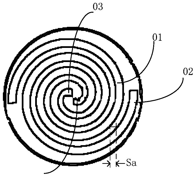
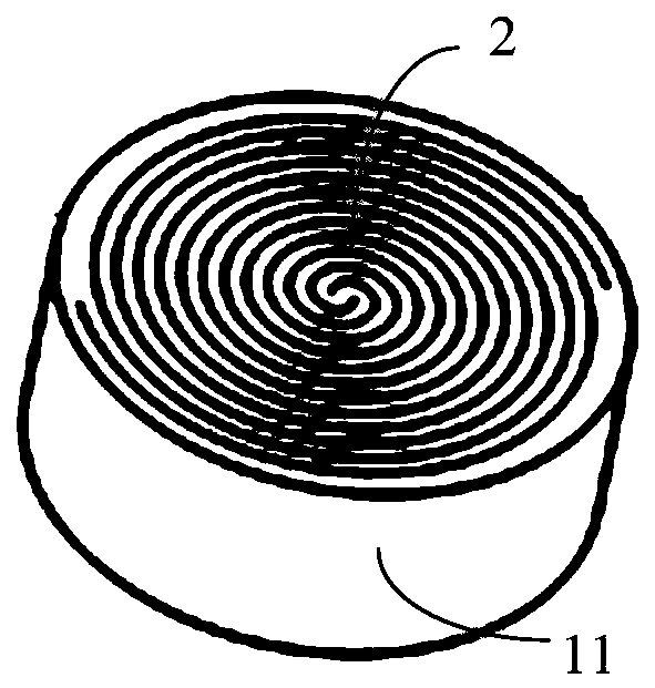
[0030] Embodiments of the present invention provide an antenna structure, such as Figure 5 As stated, the antenna structure includes:

[0031] A metal plate 1, the metal plate 1 has a first surface and a second surface arranged opposite to each other, and an accommodating groove 3 is opened on the metal plate 1, and the accommodating groove 3 is adjacent to the first surface;

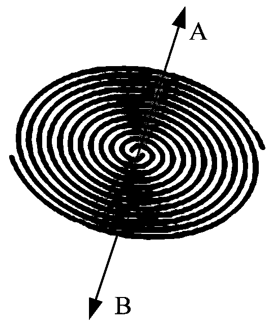
[0032] The helical radiator 2, the helical radiator 2 is installed in the...


PUM


Abstract

The present invention provides an antenna structure and a terminal. The antenna structure includes: a metal plate having a first surface and a second surface which are disposed opposite to each other,wherein metal plate is provided with receiving grooves which are adjacent to the first surface; spiral radiators installed in the receiving grooves which are in insulation arrangement with the metalplate, wherein each spiral radiator is provided with a feed end configured to connect with a feed source. According to the scheme, the problems are solved that a millimeter wave antenna disposed on the terminal occupies more space and does not facilitate the design challenge of miniaturization and the whole machine integration in order to achieve multi-band, large bandwidth, and high gain in the prior art .

Description

technical field [0001] The present invention relates to the field of communication technology, in particular to an antenna structure and a terminal. Background technique [0002] At present, millimeter-wave antennas mostly use antenna-in-package (AiP) technology, which integrates millimeter-wave array antennas, radio frequency integrated circuits (RFICs) and power management integrated circuits (PMICs) into one module. Wherein, the antenna units constituting the millimeter wave array are mainly patch antennas (patch), Yagi-Uda antennas (Yagi-Uda) or dipole antennas (dipole). These antenna units are relatively narrow-band antennas. For example, the relative bandwidth percentage of a conventional patch generally does not exceed 8%, but millimeter-wave frequency bands often require dual-band or multi-band and large bandwidth, which brings great impact to the antenna design. challenge. [0003] Among them, in order to meet the requirements of dual-band, multi-band, and multi-b...

Claims


Application Information

Patent Timeline
Patent Type & Authority Applications(China)
IPC IPC(8): H01Q1/36H01Q1/48H01Q1/50H01Q1/22
CPCH01Q1/36H01Q9/27H01Q1/2283H01Q21/08H01Q1/523H01Q5/357H01Q1/243H01Q1/50
Inventor 简宪静黄奂衢王义金
Owner VIVO MOBILE COMM CO LTD
Why Eureka
Try Eureka