Stent Graft

A technology of covered stents and thin films, which is applied in the direction of stents, blood vessels, and devices with human tubular structures, can solve problems such as endoleaks, treatment of unfavorable lesions, and surgical failures, so as to reduce endoleaks, promote the formation of thrombus, reduce effect of influence

Active Publication Date: 2021-02-26
LIFETECH SCI (SHENZHEN) CO LTD
View PDF10 Cites 0 Cited by
  • Summary
  • Abstract
  • Description
  • Claims
  • Application Information

AI Technical Summary

Problems solved by technology

When the chimney technique is used, since the aortic stent graft passes over and covers the opening of the branch vessel, and the proximal section of the branch stent and the aortic stent are arranged in parallel in the aortic vessel, the distal section of the branch stent is separated from the branch vessel. The opening extends into the branch vessels, so that in the aortic vessel, a large gap will be formed between the aortic stent and the branch stent, so that the blood flow can flow through the gap to form an endoleak, which is not conducive to the treatment of the lesion, and may even cause cause surgery to fail
[0003] Please refer to figure 1 , the proximal section of the branch stent 110 is placed in the aortic vessel 120 and arranged in parallel with the aortic stent 130, and the distal section is placed in the branch vessel 140 of the aortic vessel 120, please refer to figure 1 and figure 2 Since the aortic stent 130 and the proximal end of the branch stent 110 are arranged in parallel in the aortic vessel 120, there will be two larger gaps 150 between them, and blood will flow through these gaps 150, thereby creating an internal Leakage is not conducive to the treatment of 160 in the lesion, and it will lead to surgical failure in severe cases

Method used


Image

  • Stent Graft
  • Stent Graft
  • Stent Graft

Examples


Embodiment 1

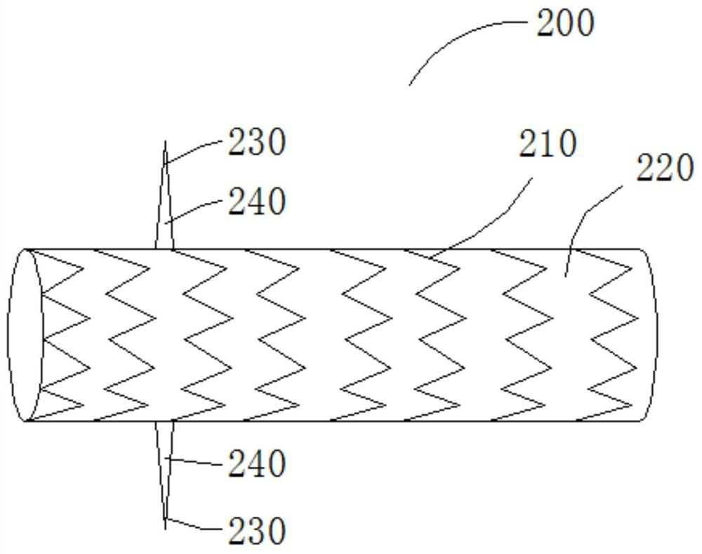
[0030] Embodiment 1 proposes a stent graft that can be used as a branch stent used in conjunction with the aortic stent graft to solve the endoleak problem during chimney operation. Please also refer to image 3 and Figure 4 The stent graft 200 includes a hollow tubular stent main body 210 with openings at both ends and a first film 220 coated on the stent main body 210. Two retaining rods 230 are arranged on the outer wall of the stent graft 200. The two retaining rods 230 The rods 230 can be arranged symmetrically or asymmetrically. The two ends a and b of each blocking rod 230 are respectively connected to the bracket main body 210, and each blocking rod 230 is provided with at least one layer of second film 240, and the second film 240 covers the blocking rod 230 through a film coating process, and the first A part of the second thin film 240 is connected with the first thin film 220 to block blood flow from the proximal end of the stent-graft 200 to flow out from the d...

Embodiment 2

[0037] The parts of the stent-graft 300 in the second embodiment that are the same as the stent-graft 200 in the first embodiment will not be repeated here. The outer wall is distributed in a spiral shape. Please also refer to Figure 6 and Figure 7 , the stent graft 300 is provided with five blocking rods 330, these blocking rods 330 are spirally spaced and evenly distributed on the outer wall of the stent graft 300, and the blocking rod 330 at the farthest end on the The blocking rod 330 at the end of the stent graft 300 overlaps when viewed from one end toward the other end. When the distance between adjacent blocking rods 330 in the axial direction of the stent graft 300 is too large, it is not conducive to forming a good blockage of the blood flow; if the distance is too small, it is difficult for the stent graft 300 to be sheathed. In the axial direction of the stent graft 300, one or more coil lengths on the stent body 310 can be spaced (such as Figure 5 The dista...

Embodiment 3

[0041] The parts of the stent-graft 400 in Example 3 that are the same as those in the stent-graft 200 in Example 1 will not be repeated here. The main difference between the two lies in that in Example 3, please refer to Figure 8-Figure 10 , the covered stent 400 is provided with two symmetrical or asymmetrically arranged blocking rods 430, and each blocking rod 430 is provided with at least one layer of second film 440, and the second film 440 is connected to the stent main body 410 in a hood shape. On the first film, and the proximal end of the second film 440 is connected with the blocking bar 430 to form an opening 450 .

[0042] The second film 440 has an arc-shaped semi-closed shape, and the value of the axial length is 2 mm to 30 mm, preferably 15 mm. It cooperates with the first film and the blocking rod 430 to form a hood-like structure 460 in the unfolded state. The number and distribution characteristics of the hood-shaped structures 460 on the stent-graft 400 are...


PUM


Abstract

The present invention relates to a stent graft, comprising a stent main body and a first film coated on the stent main body, at least two blocking rods are arranged on the outer wall of the stent grafting, each of the two blocking rods The ends are respectively connected with the stent main body, and at least one layer of second film is provided on each of the blocking rods, and the second film is connected with the first film to block the blood flow from the proximal end of the stent graft. The end flows out from the distal end of the stent-graft through the inside of the blocking rod; the blocking rod is folded and attached to the outer wall of the stent-graft in the delivery state, and rebounds to expand to the outer wall of the stent-graft after being released. The outer walls of the stent-graft intersect. The covered stent of the invention can solve the endoleak problem in the chimney operation, and reduces the difficulty of sheathing the covered stent.

Description

technical field [0001] The invention relates to the technical field of interventional medical devices, in particular to a covered stent. Background technique [0002] In the endoluminal treatment of the aorta, when the dissection breach is close to the branch vessels, so that the anchoring area of ​​the aortic stent graft is insufficient, the chimney technique or in situ fenestration technique is often used to isolate the lesion and The purpose of opening branch vessels. When the chimney technique is used, since the aortic stent graft passes over and covers the opening of the branch vessel, and the proximal section of the branch stent and the aortic stent are arranged in parallel in the aortic vessel, the distal section of the branch stent is separated from the branch vessel. The opening extends into the branch vessels, so that in the aortic vessel, a large gap will be formed between the aortic stent and the branch stent, so that the blood flow can flow through the gap to f...

Claims


Application Information

Patent Timeline
Patent Type & Authority Patents(China)
IPC IPC(8): A61F2/07
Inventor 王逸斐肖本好
Owner LIFETECH SCI (SHENZHEN) CO LTD
Why Eureka
Try Eureka