Cloth cutting device for textile production

A cutting device and cloth technology, applied in the cutting of textile materials, textiles and papermaking, mechanical cleaning, etc., can solve the problems of low cutting efficiency, low guiding efficiency, unsuitable for fixing cloth rolls of different sizes, etc., and achieve improved cutting Processing efficiency, small footprint, and the effect of ensuring health

Active Publication Date: 2019-05-10
泸溪县康葳服装有限公司
View PDF8 Cites 21 Cited by
  • Summary
  • Abstract
  • Description
  • Claims
  • Application Information

AI Technical Summary

Problems solved by technology

[0003] The existing textile cloth cutting device needs to be used with the cloth guide mechanism when cutting the textile clot

Method used


Image

  • Cloth cutting device for textile production
  • Cloth cutting device for textile production
  • Cloth cutting device for textile production

Examples


specific Embodiment approach 1

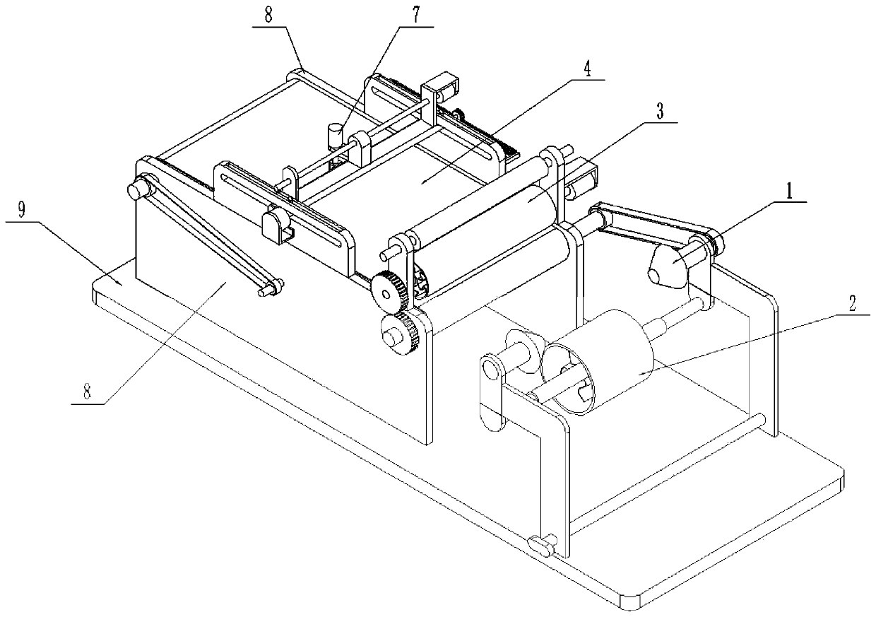
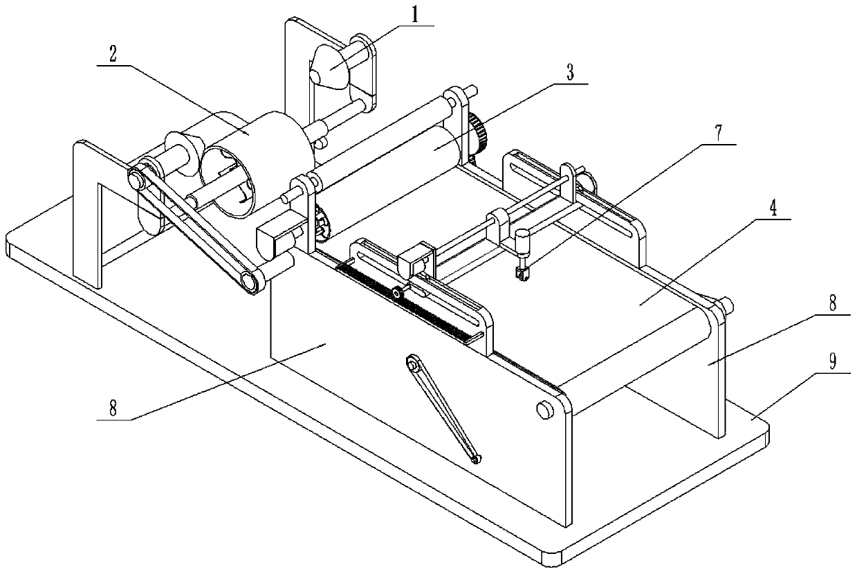
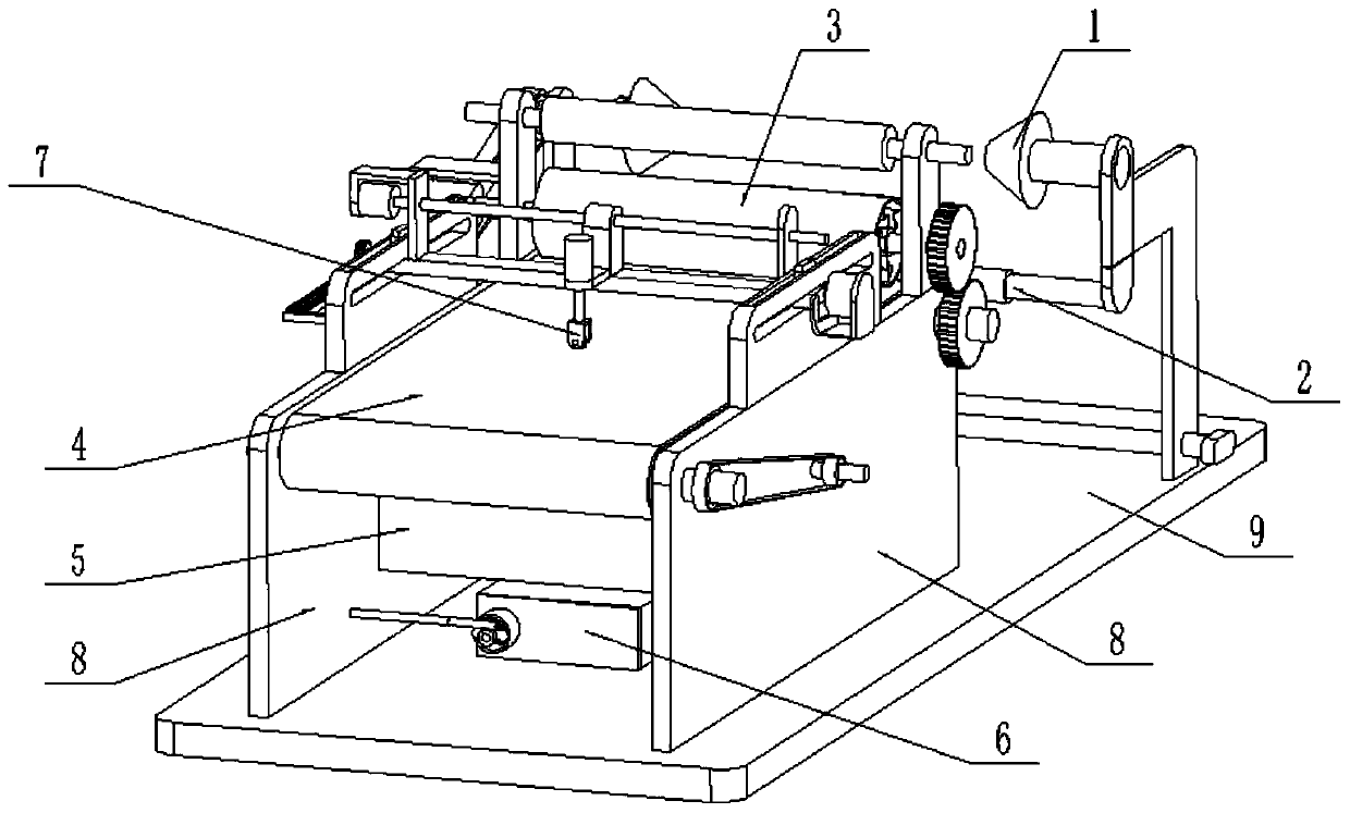
[0032] Such as Figure 1-14 As shown, the fabric cutting device for textile production includes a fabric roll fixing mechanism 1, a fabric roll pressing mechanism 2, a fabric roll guiding mechanism 3, a fabric conveying mechanism 4, a cleaning mechanism 5, a fabric debris recovery mechanism 6, and a fabric cutting mechanism 7. The side frame plate 8 and the base plate 9, the side frame plate 8 is provided with two pieces, and the two side frame plates 8 are fixedly connected to the left and right sides of the front end of the top surface of the base plate 9; the lower end of the cloth roll fixing mechanism 1 Connected to the rear end of the top surface of the base plate 9; the cloth roll pressing mechanism 2 is fixedly connected to the cloth roll fixing mechanism 1; The rear end; the cloth roll guiding mechanism 3 is meshed and driven to connect the cloth conveying mechanism 4; the cloth conveying mechanism 4 is rotated and connected to the upper end of the inner side of the t...

specific Embodiment approach 2

[0033] Such as Figure 1-14 As shown, the cloth roll fixing mechanism 1 includes a movable frame plate 1-1, a fixed frame plate 1-2, a screw rod 1-3, a distance adjustment rotary block 1-4, a circular shaft 1-5, and a cone without a cone tip. Plug 1-6, linkage shaft 1-7 and linkage pulley 1-8, the bottom surface of the movable frame plate 1-1 is connected to the top surface of the base plate 9 by sliding fit; the fixed frame plate 1-2 is fixedly connected At the rear end of the top surface of the base plate 9; the left end of the screw rod 1-3 is fixedly connected to the distance adjustment rotary block 1-4, and the right end of the screw rod 1-3 is rotatably connected to the fixed frame plate 1-2 by a bearing with seat; The movable frame plate 1-1 is connected by thread on the screw rod 1-3 between the distance adjustment rotary block 1-4 and the fixed frame plate 1-2; the circular shaft 1-5 is provided with two, one circular The left end of the shaft 1-5 is rotatably connec...

specific Embodiment approach 3

[0034] Such as Figure 1-14 As shown, the cloth roll pressing mechanism 2 includes a pressing cylinder 2-1, a first curved spring piece 2-2, a central sleeve 2-3, a compression spring 2-4, a side slide bar 2-5 and a rod seat Plate 2-6; the central sleeve 2-3 is located on the inner side of the compression cylinder 2-1; the outer surface of the central sleeve 2-3 is uniformly fixedly connected to one end of a plurality of first curved spring pieces 2-2 , the other ends of multiple first curved spring pieces 2-2 are evenly and fixedly connected on the inner wall of the compression cylinder 2-1; the side slide rods 2-5 are provided with two, and the two side slide rods 2-5 The inner sides are slidingly fitted and connected in the sliding grooves at the left and right ends of the center sleeve 2-3, and the compression springs 2-4 are provided with two, and the two compression springs 2-4 are respectively arranged in the two sliding grooves; The inner and outer ends of the spring ...


PUM


Abstract

The invention relates to the field of textile processing equipment and in particular relates to a cloth cutting device for textile production. The cloth cutting device comprises a cloth roll fixing mechanism, a cloth roll pressing mechanism, a cloth roll unwinding mechanism, a cloth conveying mechanism, a cleaning mechanism, a cloth scrap recovery mechanism, a cloth cutting mechanism, side frame plates and a base plate; totally two side frame plates are arranged; the two side frame plates are fixedly connected to the left and right sides of the front end of the top surface of the base plate; the lower end of the cloth roll fixing mechanism is connected to the rear end of the top surface of the base plate; and the cloth roll pressing mechanism is fixedly connected onto the cloth roll fixingmechanism. The cloth roll fixing mechanism and the cloth roll pressing mechanism are arranged inside the cloth cutting device, so that cloth rolls of different sizes can be fixed; and the cloth rollunwinding mechanism is arranged inside the cloth cutting device, rapid unwinding of the cloth rolls can be realized by matching the cloth roll unwinding mechanism and the cloth roll fixing mechanism,and the cloth cutting efficiency is conveniently improved.

Description

technical field [0001] The invention relates to the field of textile processing equipment, in particular to a cloth cutting device for textile production. Background technique [0002] Knitted fabrics are divided into two types according to the weaving method: weft-knitted fabrics and warp-knitted fabrics. Weft-knitted fabrics are often made of low-elastic polyester yarn or special-shaped polyester yarn, nylon yarn, cotton yarn, wool yarn, etc. Circle weaves, etc., are woven on various weft knitting machines. [0003] The existing textile cloth cutting device needs to cooperate with the cloth unwinding mechanism when cutting the textile cloth, the unwinding efficiency is low, the cutting efficiency is low, and it is not suitable for fixing cloth rolls of different sizes. Contents of the invention [0004] The object of the present invention is to provide a cloth cutting device for textile production, which is equipped with a cloth roll fixing mechanism and a cloth roll p...

Claims


Application Information

Patent Timeline
IPC IPC(8): D06H7/00D06G1/00
Inventor 杨韦韦
Owner 泸溪县康葳服装有限公司
Why Eureka
Try Eureka