Measurement method and system for center-of-gravity position

A technology of center of gravity position and measurement method, which is applied in measurement devices, testing of machine/structural components, static/dynamic balance testing, etc. The effect of stable measurement process, small equipment impact and high measurement accuracy

Active Publication Date: 2019-05-10
HUAZHONG UNIV OF SCI & TECH
View PDF4 Cites 4 Cited by
  • Summary
  • Abstract
  • Description
  • Claims
  • Application Information

AI Technical Summary

Problems solved by technology

Due to the complex structure of precision equipment and equipment and moving parts, it is difficult to determine the position of the center of gravity by theoretical calculation, and it is necessary to conduct on-site inspection through certain methods
[0003] The existing center of gravity measurement schemes generally use methods such as hoisting experiments or force sensors, but such methods are not suitable for occasions where the equipment is inconvenient to move or the system is inconvenient to install additional force sensors, especially not suitable for equipment such as photolithography machines and scanning electron microscopes. For precision equipment or instruments that are convenient for large-scale movement, the active shock absorber of its supporting parts is not convenient for installing additional force sensors
Secondly, in

Method used


Image

  • Measurement method and system for center-of-gravity position
  • Measurement method and system for center-of-gravity position
  • Measurement method and system for center-of-gravity position

Examples


Embodiment Construction

[0051] In order to make the object, technical solution and advantages of the present invention clearer, the present invention will be further described in detail below in conjunction with the accompanying drawings and embodiments. It should be understood that the specific embodiments described here are only used to explain the present invention, not to limit the present invention. In addition, the technical features involved in the various embodiments of the present invention described below can be combined with each other as long as they do not constitute a conflict with each other.

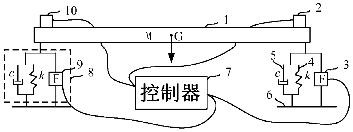
[0052] Such as figure 2 As shown, in one of the embodiments of the present invention, the 2-point supporting load 1 is a long rod with uneven mass distribution, which is supported by active shock absorbers 8 (one on each side), and each active shock absorber 8 includes a first The actuator 3, the spring 4 and if the damper 5. The foundation 6 is the source of micro-vibration. The function of ...


PUM


Abstract

The invention belongs to the technical field of ultra-precision active vibration reduction and discloses a measurement method for center-of-gravity position. The method is realized by a center-of-gravity measuring system. The center-of-gravity measuring system comprises a controller and more than two active shock absorbers, each active shock absorber cooperates with an actuator and a sensor, the active shock absorber is used for supporting a load, and a support point is formed at each active shock absorber. The measuring method comprises the following steps: S1, starting the center-of-gravitymeasuring system, the controller adjusting the output amplitude of each actuator, so that the load only has a response in the gravity direction; and S2, calculating according to the output amplitude of each actuator and the distance between adjacent support points to obtain the center-of-gravity position of the load. The invention further discloses a corresponding measurement system. According tothe measurement method, rapid identification of the center of gravity of the load of the precise active shock absorber is realized, without the help of extra sensors, the influence of the process on equipment is small, and the measuring precision is high.

Description

technical field [0001] The invention belongs to the technical field of precision vibration reduction, and more specifically relates to a method and system for measuring the position of the center of gravity. The measuring method can be used in photolithography machines, scanning electron microscopes, precision processing equipment, precision instruments, optical experiment equipment, precision medical equipment, etc. Measurement of the center of gravity of precision machining equipment. Background technique [0002] With the development of science and technology, the application of ultra-precision equipment represented by photolithography machines and scanning electron microscopes is becoming more and more extensive, and the accuracy of its manufacturing and measurement is getting closer and closer to the physical limit. In the process of micro / nano processing or measurement, environmental vibration has become a bottleneck problem restricting its accuracy. Precision process...

Claims


Application Information

Patent Timeline
IPC IPC(8): G01M1/12
Inventor 李小清陈鹏陈学东
Owner HUAZHONG UNIV OF SCI & TECH
Why Eureka
Try Eureka